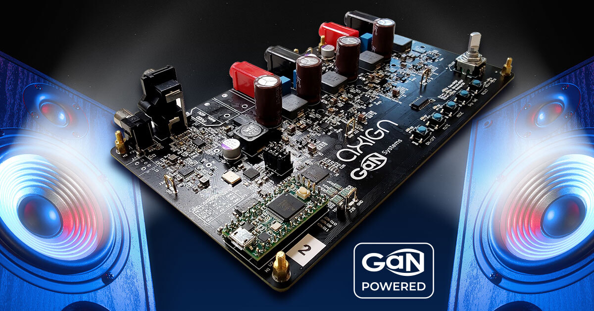
Another kit you may find interesting is the demo kit by GaN system (being acquired by Infineon), which Amir reviewed here.
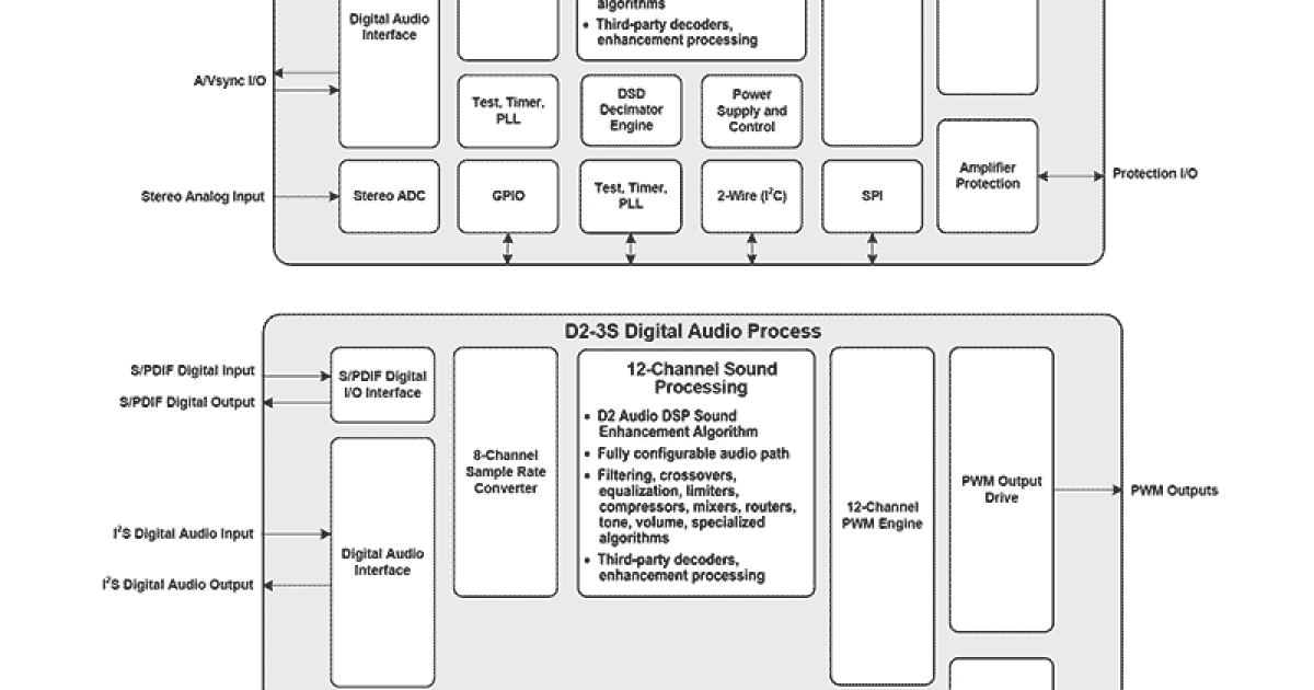
It has an onboard DSP (called D2Audio) by Renesas (who acquired it from Intersil). Here are a few links for further info (which is as much as I know about this system). My impression is that its performance seems to be limited by the Renesas controller, and is significantly below that of the Axign. GaN systems is supposed to have a reference design with the Axign controller, but I don't think GaN systems made it into an eval kit. The software for the DSP was renamed to "D2Audio Customization GUI" from "Audio Canvas III".

 gansystems.com
 www.renesas.com
 gansystems.com
It has an onboard DSP (called D2Audio) by Renesas (who acquired it from Intersil). Here are a few links for further info (which is as much as I know about this system). My impression is that its performance seems to be limited by the Renesas controller, and is significantly below that of the Axign. GaN systems is supposed to have a reference design with the Axign controller, but I don't think GaN systems made it into an eval kit. The software for the DSP was renamed to "D2Audio Customization GUI" from "Audio Canvas III".
GS-EVB-AUD-BUNDLE2-GS Evaluation Board | GaN Systems
gansystems.com
D2-92683 - Intelligent Digital Amplifier and Sound Processor
DAE-3™ and DAE-3HT™ Digital Audio Engine™ devices, System-on Chip (SoC) multi-channel digital sound processors and Class-D amplifier controllers.
500W Heatsinkless Audio Amplifier from Axign and GaN Systems Demonstrates a New World of Extraordinary Audio Performance | GaN Systems
Companies unveil revolutionary, high-efficiency Class-D amplifier at CES 2022 GaN Systems, the global leader in GaN power semiconductors and audio technology innovator Axign, debuted a new groundbreaking GaN-based 500W Class-D audio amplifier. This reference design merges best-in-class...
gansystems.com

 other than financial of course, it has been my biggest hurdle in all of this. I've mostly been depending on software for testing and simulation. I figure programs like LTSpice are mature enough that they take real world factors into consideration when running simulations so that's what I've been using. I've also got things like sigmastudio, VituixCAD, pspice, fusion360, and kicad among others, but I do not have room for a home lab at the moment. For all intents and purposes, for reasons I would rather not get into on a public forum, I'm kind of in a shoebox lol