
-
WANTED: Happy members who like to discuss audio and other topics related to our interest. Desire to learn and share knowledge of science required. There are many reviews of audio hardware and expert members to help answer your questions. Click here to have your audio equipment measured for free!
- Forums
- Audio, Audio, Audio!
- DACs, Streamers, Servers, Players, Audio Interface
- Combination Audio DAC and Headphone Amplifiers
You are using an out of date browser. It may not display this or other websites correctly.
You should upgrade or use an alternative browser.
You should upgrade or use an alternative browser.
SMSL M500 DAC and HP Amp Review
- Thread starter amirm
- Start date
Veri
Master Contributor
- Joined
- Feb 6, 2018
- Messages
- 9,603
- Likes
- 12,047
It seems most AIOs tend to be optimised for 300ohm/desktop earphones rather than low sensitivity/50mv .no one bothers to do better SNR under 50mv, esp in these all in one gears
Spoiler: it won't perform well.
Actually it may perform very well if it's designed right. Likely not to the level of the M500 but can be quite respectable. It's up to SMSL engineers.
Would be handy to put these measurements side by side with DX7 Pro like someone did with the Sabaj unit.
I've posted a side-x-side-x-side comparison of the Sabaj D5, the SMSL M500, and the Topping DX7 Pro. Hopefully that's useful to some folks here.
https://www.audiosciencereview.com/...-topping-dx7-pro-measurement-comparison.9636/
Tks
Major Contributor
- Joined
- Apr 1, 2019
- Messages
- 3,221
- Likes
- 5,500
I've posted a side-x-side-x-side comparison of the Sabaj D5, the SMSL M500, and the Topping DX7 Pro. Hopefully that's useful to some folks here.
https://www.audiosciencereview.com/...-topping-dx7-pro-measurement-comparison.9636/
Just a tip so that the images load up faster, and the forum doesn't have to host the image. Try imgur.com to upload the pictures.
maxxevv
Major Contributor
- Joined
- Apr 12, 2018
- Messages
- 1,872
- Likes
- 1,964
No, the devils are the ones that destroy the fidelity of your musical samples. If an R2R DAC performs well, it will get my recommendation. Here is an example: https://www.audiosciencereview.com/...rements-of-soekris-dac1421-multibit-dac.3956/
View attachment 37302
So leave your generalizations at the door. Here, we go by logic and what we can demonstrate.
You missed out the other elephant in the room:
https://www.audiosciencereview.com/...measurements-of-holo-audio-cyan-dsd-dac.6992/
It measures comparably with many DS chipped DACs !
have some faith.. they aren't designing as in the stone ages of the pcm1704; they are using measurement devices like the ap555x to guide their design. NOS will result in some artifacts that are unavoidable, but the chances of this popping out as a 40 SINAD device is improbably if not impossible. if that was the best they could do, they would just nix the design.
Veri
Master Contributor
- Joined
- Feb 6, 2018
- Messages
- 9,603
- Likes
- 12,047
Would be cool if someone sends in a holo spring one of these daysYou missed out the other elephant in the room:
https://www.audiosciencereview.com/...measurements-of-holo-audio-cyan-dsd-dac.6992/
It measures comparably with many DS chipped DACs !
") not that I'm an advocate of pricy boutique DACs, but it is a pretty thing imo
not that I'm an advocate of pricy boutique DACs, but it is a pretty thing imo
Last edited:
Would be cool if someone sends in a holo spring one of these days
For a preview you can look at Stereophile measurements.
In fact, we already know at least the SINAD. SMSL specs are always highly reliable. This one is rated at 0.0015% THD+N, which equals to 96db SINAD. So "OK for R2R" but certainly far from SOTA.Actually it may perform very well if it's designed right. Likely not to the level of the M500 but can be quite respectable. It's up to SMSL engineers.
In fact, we already know at least the SINAD. SMSL specs are always highly reliable. This one is rated at 0.0015% THD+N, which equals to 96db SINAD. So "OK for R2R" but certainly far from SOTA.
No, no hope for SOTA SINAD. But, if it's reasonably quiet and linear to 20 bits with support for high sampling rate over USB and a way to bypass the internal digital filter given the balanced outputs I may bite.
Last edited:
Regardless of the technical merits - or otherwise - of MQA, as someone pointed out earlier, it's trying to sell you a solution to a problem that if it did exist, doesn't exist now. Which just leaves it as a bit of a rip off, as it's not free.
Re the week-banned troll from earlier - wasn't the clue in his user name.. it just needed 2 more letters, "er" on the end of protoss.....
Re the week-banned troll from earlier - wasn't the clue in his user name.. it just needed 2 more letters, "er" on the end of protoss.....
OP
- Thread Starter
- #294
They are balanced. I have not seen a fake XLR line out output on a DAC.@amirm Could you please give your feedback on this query of the XLR outputs being "real balanced".
NielsMayer
Active Member
@amirm Could you please give your feedback on this query of the XLR outputs being "real balanced". Your tests show great results on the XLR output but I'm not sure if this means it is true balanced. Being honest I don't have any idea what this even means but before picking this up on 11/11 I'd at least like to try to understand ;-)
Here's what I wrote earlier about "fake balanced" and my hunches about it based on measurements (discussion around https://www.audiosciencereview.com/forum/index.php?threads/new-smsl-m500.8857/page-9 )
............................
If you look at the specs, you see that the balanced output has a higher dynamic range (125dB) than the unbalanced (120dB). Although it's a little counterintuitive, since the balanced output offers common mode noise rejection and overall lower real world noise .... The problem is that a balanced output requires twice as many op amps per output, which means twice as much noise. So IMHO in the real world a "real balanced output" doesn't ever have a significantly better spec than the unbalanced. For example the Dx7S has 123dB dynamic range on the XLRs versus 122dB on the RCA's.
So add the above two hunches and you get --this unit is using the same output opamps for the XLR and RCA, and using "fake balanced" outputs which looks like the "line output" below (or alternately and more reasonably, using a dual op-amp configured the same for each channel, with one output to RCA, and the other to a "fake balanced" output like this:
Fake balanced offers the same common-mode rejection (courtesy the differential input op-amp on the other end of the cable, has nothing to do with output), and the above architecture is half the cost and half the noise. Probably not as good for driving a 100ft balanced run in a pro audio install, but at least measuring better and not doing much harm in a normal amateur studio or home."
Note...
For M500 amir measured S/N:
XLR 116.6/116.8 dB
RCA 114.4/115.6 dB
and specs show dynamic range (*)
- XLR 125dB (amir measured 125 ...)
- RCA: 120dB
Note (*): for dynamic range, @amirm only measured xlr, and to do RCA "fair" you'd probably have to measure using a "fake balanced" rca-xlr cable which grounds the - line at the output end and drives the + with the RCA unbalanced out (modulo pro vs consumer levels) but gives you a "fair" common-mode noise rejection comparison entirely due to the differential input on the receiving/analyser end of the cable.
For comparison Topping DX7Pro specs
- XLR: SNR, A-weighted: >126 dB at 1 kHz
- RCA: SNR, A-weighted: >122 dB at 1 kHz
- XLR: Dynamic Range, A-weighted: >126 dB at 1 kHz
- RCA: Dynamic Range, A-weighted: >122 dB at 1 kHz
And note that for home use, and real world op-amps and cost-limits, "fake balanced" might sound better than real balanced because you get half the noise, half the distortion, half the slew-rate limitation, half the current to drive cable inductance and capacitance, half the damping factor to cancel-out line-ringing, and all the other things that come along with adding another op amp to the other side of the differential cable, instead of grounding it....
Would like teardown verification. As my unit is to be returned for refund, I'm not about to do that to my own unit, let alone any unsupported attempts to upgrade its firmware via unsupported linux....
dkinric
Addicted to Fun and Learning
Re the week-banned troll from earlier - wasn't the clue in his user name.. it just needed 2 more letters, "er" on the end of protoss.....
Pro tosser? A decidedly British insult, similar to Wanker I guess. Not generally used in USA, but thinking I need to start to use it more often.
NielsMayer
Active Member
They are balanced. I have not seen a fake XLR line out output on a DAC.
Open up a behringer. they're the king of fake-balanced. ( https://www.audiosciencereview.com/...get-dac-review-behringer-umc204hd.1658/page-5 https://www.audiosciencereview.com/...dac-review-behringer-umc204hd.1658/post-49167 "being fake balanced is an even bigger corner cut"
(from @Blumlein 88 )
From a customer review by OCDShopper on Amazon (https://smile.amazon.com/Behringer-...TF8&coliid=I2KCX53CXRWSRH&colid=1LHJSAHO9QMMU)
"Both on the product's box, as well as 2 places on the manufacturer's website, this model is said to have "Main Outputs on balanced XLR". I found this to be completely false.
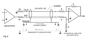
Those who know how balanced audio works know that XLR pins 1, 2, and 3 correspond to "ground", "hot", and "cold". If you output a steady sine wave (e.g. generate one with Audacity and play it), you should be able to measure (e.g. with a high impedance digital multimeter, preferably true RMS) a small AC voltage between "hot" and "ground". The voltage between "cold" and "ground" should be exactly the same, except that it's reversely phased. Consequently, the voltage measured between "hot" and "cold" will be twice the voltage between "hot" and "ground" or "cold" and "ground". (That's why balanced audio is described as having twice the headroom.)
Anyway, on this device, I found that there is always 0.00 AC volts between "cold" and "ground" and equal voltage hot-to-ground and hot-to-cold. (If you measure resistance w/o power or signal connected, you'll find only about 100 ohms between cold and ground.) So, if you use this device, you will not get balanced audio output even on the main channels (as advertised), much less on the other outputs, and this output will be much more susceptible to picking up interference."
and from a review by CameraTim (http://www.cameratim.com/reviews/audio/behringer-u-phoria-umc404hd-audio-interface/)
"It's a four-channel line-out digital to analogue converter (DAC), with ¼″ TRS and RCA jacks for balanced and unbalanced connections. They're not actually true balanced outputs, they're what's known as “impedance balanced” (one leg of the output is driven (tip), the other leg (ring) is terminated to ground with a resistance similar to output-driver's impedance).
I can't say that I like impedance-balanced connections. If not done precisely (and it rarely is—a simple resistor to ground does not have the same characteristics as the output stage of the driven half of the allegedly balanced output), CMRR will be poor. You don't have the isolation that a fully-floating (non-ground-referenced) connections will have. You get no signal if someone has made an unbalanced connection by grounding pin two instead of pin three. And some balanced-input equipment doesn't work too well when only one leg is driven (I have one mixer like that). While some may say I'm being picky, haveing the best possible noise-rejection is important when working in electrically noisy environments, especially when you have leads going all over the place."
Also, "fake balanced" is not "fake". As in it performs just as well as "real balanced" and often better because of only one output op amp.
"fake balanced" is balanced courtesy the common mode rejection of the input differential amplifier on the amplifier or analyzer at the other end of the DAC cable.
Some believe that even the differential input amp on the receiving end is "fake" and that only transformers are "real"
https://d1b89e86-9572-4311-9f80-600...d/3e7c3b_63560d02b6e242e3aa42d225f94a131e.pdf
So the majority of these “balanced inputs” are in fact just two single ended inputs, there is no “balanced” about it. If you can imagine two equal weights, when they sit on the butcher’s counter are they balanced? No. If you pick one up does it influence the other? No. It’s only when the weights are placed one on each side of the scale are they said to be “in balance” or “balanced”. Most of the audio inputs which purport to be balanced are like the two separate weights, they are unconnected inputs which, when a signal is applied to one, will produce an output which is 180 degrees out of phase relative to the other. As we stated before, if the drive to each input is EXACTLY the same, and assuming the circuit has a big window before some kind of non-linearity upset the situation then you get zero output. But to achieve even 60dB of rejection you need calibration lab style resistors and components (and remember even the cable is part of the circuit) on both the transmitter and receiver ends of the transmission line. When you start to look at what a transformer can achieve, of the order of 120dB, which is 1000,000:1 then this scenario is just impossible. You could upset the symmetry of the circuit by just thinking about it. Just when you thought the “actively balanced” circuit was leaning on the ropes with a bleeding nose and glazed eyes, it receives two more vicious blows. Both relate to the amount of common mode signal that the circuit can handle before it starts doing something funky and unpredictable. The input circuitry of the op-amp or other circuit will have a (sometimes very limited) common mode range over which the component is linear. Outside that range and it becomes nonlinear and creates distortion. Nonlinearities at hum frequencies will upset the symmetry of the circuit and will drastically decrease the CMRR of the overall circuit. And of course the signal you’re actually interested in gets distorted as well. Normally we don’t expect to see a great deal of common mode hum voltage on the transmission line, if there’s a lot here, it probably means there’s a fault with grounding. It’s more of a problem at high frequencies, into the radio and microwave region, generated for example my mobile phones. At those frequencies the op-amp’s open loop gain will have dropped down to nothing, so the circuit doesn’t work properly anymore, That doesn’t mean that the circuit won’t respond to the RF, due to it’s nonlinearity it will demodulate the signal. There are various theories, which attribute “the transistor sound” to RF interference. For example, a decent op-amp might have a slew rate of 10V/us that means that its output can change by 10v in 1 microsecond. That might seem pretty fast, but consider a 1GHz signal, mobile phone kind of frequency. At 1GHz, 1.6mV of signal is slewing at 10V/us. It doesn’t take a lot of it to completely overload and screw up such an active input which all manners of distortions resulting. The transformer just doesn’t suffer this problem; a decently designed transformer component will have one or even two internal screens between the primary and secondary windings. These screens shield the secondary from the primary and prevent RF from getting across. The transformer’s natural high frequency limit (somewhat over 200kHz for most Audio Note™ units) prevents even differential mode hash getting to the input stage.
Last edited:
Tks
Major Contributor
- Joined
- Apr 1, 2019
- Messages
- 3,221
- Likes
- 5,500
@NielsMayer
Wouldn't fake balanced be the best then for hooking up a DAC to an amp for example at home in a stack configuration? You get the benefits(and then some with respect to noise), but simply lose out on the whole "can run longer lengths" ordeal? And since it's a stack where you're using 1ft, or even half a foot long cables, length is never a concern?
Wouldn't fake balanced be the best then for hooking up a DAC to an amp for example at home in a stack configuration? You get the benefits(and then some with respect to noise), but simply lose out on the whole "can run longer lengths" ordeal? And since it's a stack where you're using 1ft, or even half a foot long cables, length is never a concern?
NielsMayer
Active Member
Open up a behringer. they're the king of fake-balanced.
Over at Peavey and Mackie, they renamed behringer's teutonic "fake balanced" as "impedance balanced" ... which is why they pay marketing the big bucks... (Behringer marketing previously sold sushi as cold dead fish).
https://www.harmonycentral.com/forums/topic/210292-xlr-outputs-on-mixerbig-deal/
I guess they had to diseappear the article explaining "impedance balanced" but i found it on the internets!
https://web.archive.org/web/2002061...ndweb.com/install/sac/n27/rick/balout-1.shtml
Executive summary:

Similar threads
- Replies
- 128
- Views
- 31K
- Replies
- 29
- Views
- 3K
- Replies
- 51
- Views
- 40K
- Replies
- 12
- Views
- 657