• WANTED: Happy members who like to discuss audio and other topics related to our interest. Desire to learn and share knowledge of science required. There are many reviews of audio hardware and expert members to help answer your questions. Click here to have your audio equipment measured for free!

UMIK-1 or any USB MIC unsuitable for timing measurements?

gnarly

Major Contributor
Joined
Jun 15, 2021
Messages
1,042
Likes
1,479
For acoustic reference, the impulse of the acoustic reference determines t=0, so the location of measurement impulse is the difference in time of flight between the acoustic reference and DUT, not the distance of DUT to mic.

For electrical loopback, impulse of the electrical loopback is same point in time as the sound leaves the speaker, so location of impulse will be always the physical time of flight of DUT to the mic, always. For this reason, instruction for VituixCAD measurement with REW suggest to place the mic 1 meter from the baffle surface, and use 2.907ms of timing offset, or 1m time of flight so measurements are captured with positioning relative to the baffle surface.

Acoustic reference speaker should be a high frequency driver like a tweeter, do not a large woofer for an acoustic reference. You can measure whatever you want, but the acoustic reference output gets set to a different output channel, connected to a high frequency capable driver.

Yeah, all that is why I've avoided acoustic reference entirely, for years.
A surrogate acoustic reference like a separate tweeter, is a complete non-starter for the type speaker tuning I like to do, which gets time and phase alignment to within a few samples.
 

dcibel

Member
Joined
Feb 8, 2021
Messages
47
Likes
52
0 sample error should be the goal, accomplished with dual channel :)

"Within a few samples" may not sound like much as far as distance goes, and at <1kHz may not present much of a problem, but can present significant phase error at high frequencies.

Take 5kHz for an example.
At 44.1kHz sample rate, 1 sample represents 7.8mm of error, or +/- 40 degrees at 5kHz
At 96kHz sample rate, 1 sample represents 3.58mm of error, or +/- 19 degrees at 5kHz.

Presented as a pretty graph. 0 deg flat line would be 0 error. Here, 1 sample error at 44.1kHz is shown as green dashed. 1 sample error at 96kHz is shown in red.
1712101238947.png


(yes, nearly 180 deg phase shift at 20kHz for a single sample error at 44.1kHz)
 
Last edited:
OP
L

levimax

Major Contributor
Joined
Dec 28, 2018
Messages
2,416
Likes
3,558
Location
San Diego
I am getting my new Mic shortly and looking over the VituixCAD/ REW documents I have some questions which are probably obvious but not to me.

I have never used the "phantom power" on my interface before and 48 volts sounds like a lot and I will be hooking up the Mic input to the "output" for the loopback and similar depending if it is for impedance or 2 channel measurements. Anyway do I have to worry about the 48 volts causing any trouble and if so what do I need to watch out for? Thanks
 

dcibel

Member
Joined
Feb 8, 2021
Messages
47
Likes
52
48V output is only capable of a few mA of current, so you're unlikely to cause any real damage. But here's my best advice.

On a USB audio interface, 48V phantom power only exists on the XLR pins. The inputs are combo jacks that accept both XLR and TRS, so use TRS for all non-mic connections and you are guaranteed to never have a problem.

You'll notice TRS connections used in my jig:
 

gnarly

Major Contributor
Joined
Jun 15, 2021
Messages
1,042
Likes
1,479
0 sample error should be the goal, accomplished with dual channel :)

"Within a few samples" may not sound like much as far as distance goes, and at <1kHz may not present much of a problem, but can present significant phase error at high frequencies.

Take 5kHz for an example.
At 44.1kHz sample rate, 1 sample represents 7.8mm of error, or +/- 40 degrees at 5kHz
At 96kHz sample rate, 1 sample represents 3.58mm of error, or +/- 19 degrees at 5kHz.

Presented as a pretty graph. 0 deg flat line would be 0 error. Here, 1 sample error at 44.1kHz is shown as green dashed. 1 sample error at 96kHz is shown in red.
View attachment 360954

(yes, nearly 180 deg phase shift at 20kHz for a single sample error at 44.1kHz)
That's a good demonstration of the amount of phase rotation per sample. Not sure how many folks are aware of that.

For 5kHz and up, it's pretty easy to both measure "to-the-sample", and set delays to-the sample, if using any kind of decent DSP.
I've found dual-channel repeatability is near 100%, barring outdoor wind or significant in-room airflow, between speaker and mic.

Lower frequencies, not so easy.. Get's increasingly difficult to get repeatable 'to-the-sample' timings the lower freq goes.
Just the nature of linear FFT, as I'm sure you know.

That's the reason I said earlier that my goal is get time and phase alignment to within a few samples....to allow for all cases, such as for any xover below a few hundred Hz.
I mean, just try and get a to-the sample lock on a sub,.... unless outdoors in fully ideal conditions.

No point thinking I can get alignment more precise than I can even measure.
Nice that a few samples means less and less to phase as freq decreases, to counterbalance measurement errors, huh?
 

JohnPM

Senior Member
Technical Expert
Joined
Apr 9, 2018
Messages
344
Likes
922
Location
UK
Do you have a comment on the issues with making timing measurements with a USB Mic vs a 2 channel loopback analog Mic in REW ?
Acoustic ref with a USB mic using a separate speaker to the one being measured can provide a stable reference even for off-axis measurements within the limits of the mic, but an analog mic and a loopback connection are better. Lack of (or unreliable) response calibration data has been an issue for lower cost analog mics, however. The acoustic ref option was developed to provide USB mic users with a way of getting timing information that isn't otherwise available. USB mics provide a relatively low cost way to get acoustic measurements with reasonable response accuracy and calibrated levels. They aren't a universal tool for all audio measurement purposes.
 

gnarly

Major Contributor
Joined
Jun 15, 2021
Messages
1,042
Likes
1,479
Acoustic ref with a USB mic using a separate speaker to the one being measured can provide a stable reference even for off-axis measurements within the limits of the mic, but an analog mic and a loopback connection are better. Lack of (or unreliable) response calibration data has been an issue for lower cost analog mics, however. The acoustic ref option was developed to provide USB mic users with a way of getting timing information that isn't otherwise available. USB mics provide a relatively low cost way to get acoustic measurements with reasonable response accuracy and calibrated levels. They aren't a universal tool for all audio measurement purposes.

Knowing that they are individually calibrated, as you confirmed, I think they could make a great calibration tool for lower cost analog mics.
Seems to me, i could use both the UMIK's measured SPL and frequency response, as targets to match my analogs.

I've been doing this with a half-dozen ECM8000's used for multi-mic, matching them to my best mic an EMX 7150 which comes with calibration files.
(Along with a REED SC-05 SPL calibrator).

Cant see why a UMIK-1 couldn't replace both a more expensive calibrated analog mic, and a SPL calibrator, for making matches with the ECM8000's.
 
OP
L

levimax

Major Contributor
Joined
Dec 28, 2018
Messages
2,416
Likes
3,558
Location
San Diego
Cant see why a UMIK-1 couldn't replace both a more expensive calibrated analog mic, and a SPL calibrator, for making matches with the ECM8000's.
While the UMIK-1 and 2 are individually calibrated that does not mean they are going to be "reference" Mic's. Looking at this example https://www.mtg-designs.com/tips-tricks-tests/measurement-mic-tests/fr-mic-compare it looks like while the calibration files "help" they are not perfect and not consistent. For room EQ these Mics are fine... to be used as a "reference" for calibrating other Mic's maybe not. If you were going to do this it looks like the Cross Spectrum Labs calibration would be very helpful.
 

gnarly

Major Contributor
Joined
Jun 15, 2021
Messages
1,042
Likes
1,479
While the UMIK-1 and 2 are individually calibrated that does not mean they are going to be "reference" Mic's. Looking at this example https://www.mtg-designs.com/tips-tricks-tests/measurement-mic-tests/fr-mic-compare it looks like while the calibration files "help" they are not perfect and not consistent. For room EQ these Mics are fine... to be used as a "reference" for calibrating other Mic's maybe not. If you were going to do this it looks like the Cross Spectrum Labs calibration would be very helpful.
That's not my take. I think a factory UMIK-1/2 or Cross Spectrum anything are gonna all be too close to matter.....
mainly because there is simply a lot of slippage/variance in all of them.
Even in more expensive mics.

So really, if I'm willing to use any particular mic that I deem fine for room EQ work, or DIY speaker building, .....
what's the difference in using it, or clones I matched to it?
I'd honestly rather have consistently over accuracy, as long as not too inaccurate.

I just looked at the cal file for the UMIK-1 purchased 10 years ago. Has about 60 frequency calibration adjustments per octave.
My ISEMCon has 6 per octave, and if i remember right from a measurement & mic workshop I attended, Earthworks have 12 per octave.

So apart from the physical quality of the mic and capsule, it seems to me the quality of the calibration device used to generate cal files, and then degree of frequency resolution applied ought to be the significant other variables.

Anybody have a Cross Spectrum file....? Curious, how many freq adjustments per octave?
 

gnarly

Major Contributor
Joined
Jun 15, 2021
Messages
1,042
Likes
1,479
The MiniDSP Umik .cal files are 615 points. The CSL .cal files are 1500 points. A comparison:
Thanks !

edit: just thinking out loud....
The CSL files equal about 150 points per octave (PPO).
REW Analysis section defaults to 96 PPO log spacing.

Has me wondering how CSL gets to 1500 points total.
Are the points equal per octave, or linearly spaced?

Surely equal per octave, I hope.
If so, I wonder what kind of device and FFT program they use to calibrate with........
 
Last edited:
OP
L

levimax

Major Contributor
Joined
Dec 28, 2018
Messages
2,416
Likes
3,558
Location
San Diego
Playing around with my new Mic and some practice nearfield measurements I notice some issues due to reflections from the Mic and or Mic holder. I have one of those cheap Mic holders from Amazon but it is pretty flexible in the ways that it can be configured. What is the "best" or "ideal" way to arrange the Mic holder to reduce or eliminate reflections interfering with nearfield measurements?
 

Blumlein 88

Grand Contributor
Forum Donor
Joined
Feb 23, 2016
Messages
20,866
Likes
37,868
Playing around with my new Mic and some practice nearfield measurements I notice some issues due to reflections from the Mic and or Mic holder. I have one of those cheap Mic holders from Amazon but it is pretty flexible in the ways that it can be configured. What is the "best" or "ideal" way to arrange the Mic holder to reduce or eliminate reflections interfering with nearfield measurements?
I've taken some PVC in a size that just allows the mic to slide thru it. 3 feet is enough. You can probably get a mic holder for the PVC, slide the mic out to the end until it sticks out at least for the skinny part. I also snugged some foam around it as it goes into the PVC.

Using one of the telescoping stands so the mic is at the end of a boom seems to work about as well.

1712254339645.png
 

gnarly

Major Contributor
Joined
Jun 15, 2021
Messages
1,042
Likes
1,479
Playing around with my new Mic and some practice nearfield measurements I notice some issues due to reflections from the Mic and or Mic holder. I have one of those cheap Mic holders from Amazon but it is pretty flexible in the ways that it can be configured. What is the "best" or "ideal" way to arrange the Mic holder to reduce or eliminate reflections interfering with nearfield measurements?
Welcome to the world of acoustic measurements ! :)

Just wrap some foam around it....or if that's too little a fix, make a wand to mount to the side of the mic to extend the mic; and then wrap that with foam....and then....
....it never ends LOL.....
Frankly ime/imo, the 'issues" with acoustic measurements get ignored more and more, the more meas you take. I think it becomes more a matter of understanding why the issues are there, than one of eliminating them.
 
OP
L

levimax

Major Contributor
Joined
Dec 28, 2018
Messages
2,416
Likes
3,558
Location
San Diego
I've taken some PVC in a size that just allows the mic to slide thru it. 3 feet is enough. You can probably get a mic holder for the PVC, slide the mic out to the end until it sticks out at least for the skinny part. I also snugged some foam around it as it goes into the PVC.

Using one of the telescoping stands so the mic is at the end of a boom seems to work about as well.

View attachment 361353
The picture looks like what I have. In the picture the boom is at about a 45 degree angle. The boom can be "horizontal" / 0 degrees or "vertical" / 90 degrees. Which is preferred?
 

Blumlein 88

Grand Contributor
Forum Donor
Joined
Feb 23, 2016
Messages
20,866
Likes
37,868
The picture looks like what I have. In the picture the boom is at about a 45 degree angle. The boom can be "horizontal" / 0 degrees or "vertical" / 90 degrees. Which is preferred?
Probably close to horizontal. I've usually used it at maybe 30 degrees elevation. I'm surprised that would cause reflections at a level you would care about, but maybe so.
 

Dave Bullet

Member
Joined
Oct 30, 2022
Messages
68
Likes
100
Whilst not the prettiest thing in the world, I found a PVC boom pole majorly reduced high frequency ripple / reflections that clips and the mic stand itself introduces. Heres the original setup and PVC pole in question:
1712276451710.png

1712276207810.png

RED is the original clip based mic mounting. BLUE is the PVC pole boom:
415649522_24624168210562282_1902384161010492036_n.jpg
 
OP
L

levimax

Major Contributor
Joined
Dec 28, 2018
Messages
2,416
Likes
3,558
Location
San Diego
Whilst not the prettiest thing in the world, I found a PVC boom pole majorly reduced high frequency ripple / reflections that clips and the mic stand itself introduces. Heres the original setup and PVC pole in question:
View attachment 361441
View attachment 361440
RED is the original clip based mic mounting. BLUE is the PVC pole boom:
415649522_24624168210562282_1902384161010492036_n.jpg
I am definately noticing ripples similar to the red plots. Is the difference reflections or damped vibrations?
 

Dave Bullet

Member
Joined
Oct 30, 2022
Messages
68
Likes
100
I am definately noticing ripples similar to the red plots. Is the difference reflections or damped vibrations?

Reflections from the mic clip and stand. I doubt it's vibration related

The only difference between red and blue in my graph is mic mounting. The placement drive level and environment were pretty much identical between measurements
 

Blumlein 88

Grand Contributor
Forum Donor
Joined
Feb 23, 2016
Messages
20,866
Likes
37,868

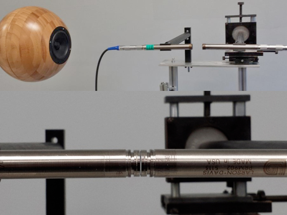
Middle of the article on free field acoustic calibration they say the microphone should be mounted on a rod the same diameter as the microphone or reflections will interfere.
1712286366857.png
 
Top Bottom