
-
WANTED: Happy members who like to discuss audio and other topics related to our interest. Desire to learn and share knowledge of science required. There are many reviews of audio hardware and expert members to help answer your questions. Click here to have your audio equipment measured for free!
- Forums
- Audio, Audio, Audio!
- DACs, Streamers, Servers, Players, Audio Interface
- Digital To Analog (DAC) Reviews and Discussion
You are using an out of date browser. It may not display this or other websites correctly.
You should upgrade or use an alternative browser.
You should upgrade or use an alternative browser.
Let's develop an ASR inter-sample test procedure for DACs!
- Thread starter splitting_ears
- Start date
")
popej
Active Member
- Joined
- Jul 13, 2023
- Messages
- 281
- Likes
- 185
Do I understand it correctly? You not only get distortion but aliased frequencies too?

- Joined
- Aug 1, 2019
- Messages
- 126
- Likes
- 109
Your math for ERB is fine. It is your knowledge of the topic that is the problem. ERB is a simplification of auditory filter bank at one loudness level. It is inappropriate to use as is for audibility of noise. I provide a reference from Stuart in the link I gave you on this. Importantly, if you read the second reference, Dynamic-Range Issues in the Modern Digital Audio Environment, from J. AES, you will see this listening test:
View attachment 323306
As I have highlighted, audibility threshold for such a wideband noise can even go down to negative SPL level of -2 dB. And this is for mono. For stereo the noise adds, lowering the threshold even more.
Also notice how environmental noise did not impact the result. The paper goes into more detail on how directional noise is more audible than diffused noise in a room.
Good paper! Will find and read.
L. Fielder (Dolby) did a lot of work on noise audibility (including perception "under program") a long time ago, like 1970s (?). I'll have to dig up those papers. IIRC, his results were surprising and counterintuitive. In addition to low-level noise, we should also look at basic waveform integrity at very low levels. Distortions / uncertainty in waveform may translate into poor imaging. Such signal aberrations are not really quantifiable by THD numbers at such low levels -- better for FFT analysis. Visual wave analysis is also instructive. For instance, here's a screen shot of one of today's lowest-noise DACs with a 25uVrms sine wave (-106dBFS I think). In our experience, this isn't audible as "distortion" -- but can be audible as image smear. Every acoustic recordist I know will tell you that sound-field accuracy is best heard at the very lowest levels -- just before the reverb tail disappears into the blackness of the room (or, in this case, the electronics). The correlation between very low level waveform distortion and sound-field / image purity is repeatable in blind tests, in our experience.
By the way, we can't accurately view/measure 25uV DAC sine waves directly on our AP2722. At this level, the broadband noise of the AP (-121dBu) starts corrupting the pure sine wave trace. To overcome this, we insert an extreme low-noise preamp at 65dB gain after the DAC (-133dBuEIN), and then calibrate the AP scale back to its proper reading. Below around 15uV or so, the quiescent noise of the 65dB preamp starts corrupting the visible sine trace, which I think would define the dynamic limits of today's best audio test path.
Attachments
AnalogSteph
Major Contributor
Both K3 versions have Type C connectors. Is it the older one with AK4452 or the newer one (K3 2021) with ES9038Q2M?Below are spectrograms of outputs of a few things I have lying around:
- DragonFly Red
- Fiio K3 (USB-C) with and without gain
OP
splitting_ears
Member
This is definitely an issue. So much so that I put it in my AES paper as DACs clearly have lower noise floor than AP. I suggested they either improve the front-end or build in noise amplifier as you deployed.By the way, we can't accurately view/measure 25uV DAC sine waves directly on our AP2722. At this level, the broadband noise of the AP (-121dBu) starts corrupting the pure sine wave trace. To overcome this, we insert an extreme low-noise preamp at 65dB gain after the DAC (-133dBuEIN), and then calibrate the AP scale back to its proper reading. Below around 15uV or so, the quiescent noise of the 65dB preamp starts corrupting the visible sine trace, which I think would define the dynamic limits of today's best audio test path.
danadam
Addicted to Fun and Learning
- Joined
- Jan 20, 2017
- Messages
- 995
- Likes
- 1,546
Isn't this aliasing a distortion too? Or did you mean harmonic distortion specifically?Do I understand it correctly? You not only get distortion but aliased frequencies too?
AFAIU things, I'd expect aliasing if they oversampled by non-integer factor. Maybe it's some kind of IMD from somewhere?
Anyway, here's how the recorded waveform looks:
And here's another look at frequency domain, a spectrum for each second:
And lastly, peak and rms values for each second:
Code:
Recorded Peak  Recorded RMS      Input True Peak
L      R       L      R
-4.22  -4.20   -7.23  -7.21   -  -0.6
-4.12  -4.10   -7.13  -7.11   -  -0.5
-4.02  -4.00   -7.03  -7.01   -  -0.4
-3.92  -3.90   -6.93  -6.91   -  -0.3
-3.82  -3.80   -6.83  -6.81   -  -0.2
-3.72  -3.70   -6.73  -6.71   -  -0.1
-3.62  -3.60   -6.63  -6.61   -  +0
-3.52  -3.50   -6.53  -6.51   -  +0.1
-3.42  -3.40   -6.43  -6.41   -  +0.2
-3.31  -3.30   -6.33  -6.31   -  +0.3
-3.18  -3.17   -6.23  -6.21   -  +0.4
-3.11  -3.09   -6.12  -6.10   -  +0.5
-3.01  -3.00   -6.03  -6.01   -  +0.6
-2.92  -2.90   -5.95  -5.93   -  +0.7
-2.88  -2.87   -5.88  -5.86   -  +0.8
-2.88  -2.88   -5.81  -5.79   -  +0.9
-2.89  -2.88   -5.74  -5.73   -  +1.0
-2.89  -2.89   -5.69  -5.67   -  +1.1
-2.90  -2.89   -5.64  -5.62   -  +1.2
-2.90  -2.90   -5.58  -5.57   -  +1.3
-2.90  -2.89   -5.53  -5.52   -  +1.4
-2.90  -2.89   -5.49  -5.47   -  +1.5
-2.90  -2.89   -5.44  -5.43   -  +1.6
-2.90  -2.89   -5.40  -5.38   -  +1.7
-2.90  -2.89   -5.35  -5.34   -  +1.8
-2.90  -2.89   -5.31  -5.30   -  +1.9
-2.90  -2.89   -5.27  -5.25   -  +2.0
-2.90  -2.89   -5.23  -5.21   -  +2.1
-2.90  -2.89   -5.19  -5.18   -  +2.2
-2.90  -2.89   -5.16  -5.15   -  +2.3
-2.90  -2.90   -5.12  -5.11   -  +2.4
-2.90  -2.90   -5.09  -5.08   -  +2.5
-2.90  -2.90   -5.06  -5.05   -  +2.6
-2.91  -2.90   -5.02  -5.01   -  +2.7
-2.91  -2.90   -4.99  -4.98   -  +2.8
danadam
Addicted to Fun and Learning
- Joined
- Jan 20, 2017
- Messages
- 995
- Likes
- 1,546
Right, I must have confused it with E10k. It's K3 with ESS.Both K3 versions have Type C connectors. Is it the older one with AK4452 or the newer one (K3 2021) with ES9038Q2M?
KSTR
Major Contributor
It is extremely hard if not outright impossible to have lowest possible noise and full protection to 100V++ at the same time in a universal analog front-end. I think this is a problem only the user can solve. If you need high gain and lowest noise, chain in your own favorite low-noise preamp and take care you don't kill its inputs.This is definitely an issue. So much so that I put it in my AES paper as DACs clearly have lower noise floor than AP. I suggested they either improve the front-end or build in noise amplifier as you deployed.
Last edited:
KSTR
Major Contributor
I think we are going in circles here.
As of yet, we have no evidence that clipped ISO's are audible compared to non-clipped ISO's with any kind of signal that reasonably resembles music. The steady-state fs/4@45° signal does not need to apply which goes without explanation. And even with this signal the hard-clipping is most certainly inaudible unless you're a bat.
OTOH, other types of ISO distortion, like the infamous wraparound, don't need any further testing as those produce annoying clicks which everybody will readily identify.
What we need is a at least one music track that is "not crushed to death" like someone said but contains quite a few ISO's, and the higher the ISO's the better, of course.
Then I'd happily volunteer to prepare a set of files for blind testing with various clipping thresholds, as outlined in some previous post of mine.

Correlation between sample rate and audible frequency?
No -- it isn't ultrasonic. I don't understand why this misconception persists; perhaps some people are confusing noise shaping with ringing. Totally different concepts. The ringing is just an effect of taking out >fs/2 frequencies from the signal. They have no frequency components
www.audiosciencereview.com
KSTR
Major Contributor
Thanks for that, I think this would meet the requirement (ISO's reaching +5dBFS) even though it's pretty synthetic (generated by a general MIDI arrangement?). I'll give it a try...Like this?Correlation between sample rate and audible frequency?
No -- it isn't ultrasonic. I don't understand why this misconception persists; perhaps some people are confusing noise shaping with ringing. Totally different concepts. The ringing is just an effect of taking out >fs/2 frequencies from the signal. They have no frequency components
You can scroll up to read the previous posts, it is a track released on a CD.Thanks for that, I think this would meet the requirement (ISO's reaching +5dBFS) even though it's pretty synthetic (generated by a general MIDI arrangement?). I'll give it a try...
As for the synthesis, these kinds of sound are generally called Chiptune. I recorded the analog output of my Game Boy in the post below (hardware.flac in the attachment).

Here is a fairly accurate representation of an emulator , rendered the same music using the same sample rate (192kHz).
There are some differences (e.g channel balance) from the hardware recording and of course high noise floor, but I bought the hardware in 1990, so all kinds of aging and defects can happen.
popej
Active Member
- Joined
- Jul 13, 2023
- Messages
- 281
- Likes
- 185
I have expected anti-aliasing (reconstruction) filter to work. But maybe actually we see distortion caused by clipping in anti-aliasing filter.Isn't this aliasing a distortion too? Or did you mean harmonic distortion specifically?
danadam
Addicted to Fun and Learning
- Joined
- Jan 20, 2017
- Messages
- 995
- Likes
- 1,546
Ah! So by "aliases" you meant those big spikes at multiples of 11k and not the small ones at about 5k and 17k? Yes, I think they are the result of clipping in the oversampling filter[*] (which I would call anti-imaging, not anti-aliasing).I have expected anti-aliasing (reconstruction) filter to work. But maybe actually we see distortion caused by clipping in anti-aliasing filter.
4x upsampling not clipped:
 and clipped:
Late edit:
[*] at least the odd multiples
Last edited:
popej
Active Member
- Joined
- Jul 13, 2023
- Messages
- 281
- Likes
- 185
Yes, alias for Fs/4 is the same frequency as its 3-rd harmonic.Ah! So by "aliases" you meant those big spikes at multiples of 11k
Looks like a perfect explanation, what is happening in a decent DAC without headroom.4x upsampling not clipped:
Last edited:
KSTR
Major Contributor
Here we go. File is mono content, so only one channel was processed in the following.Thanks for that, I think this would meet the requirement (ISO's reaching +5dBFS) even though it's pretty synthetic (generated by a general MIDI arrangement?). I'll give it a try...
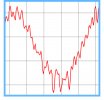
Original track, at the largest ISO with more than +5dBFS peak level which is beyond what any DAC I'm aware of would handle without clipping.
Reference track (upsampled to 705.6kHz 32 bit, -6dB gain applied, downsampled to 176.4 16bit):
Clipped (same as above, with hard-clipping at -6dBFS before the final downsampling):
Note: The "dimple on the roof" comes from the downsampling as theory says it should (ringing from the linear phase resampling).
Now let's have some fun comparing the two versions (ABX logs welcomed). I didn't bother as I'm heavily biased anyway towards "no difference" from previous experiences.
I'm aware that this simple test might not fully represent what could happen in practice (notably the analog output stage of DAC might run into saturation with a sticky recovery even when the DAC chip itself could handle +6dBFS peaks properly). But is a starting point at least.
Attachments
popej
Active Member
- Joined
- Jul 13, 2023
- Messages
- 281
- Likes
- 185
I did the same and tried. Can't hear the difference. But there is difference in spectrum over 22kHz.Now let's have some fun comparing the two versions (ABX logs welcomed).
Here 4x oversampled and -6dB version:
Then 4x oversampled, clipped at 0dBFS and -6dB:
KSTR
Major Contributor
Yes, and that's the natural consequence of the clipping.But there is difference in spectrum over 22kHz.
Here we go. I did 2 passes. First pass scoring 9/10, taking time to get familiar with the tracks; then a second pass scoring 10/10, during which I was faster.Here we go. File is mono content, so only one channel was processed in the following.
Original track, at the largest ISO with more than +5dBFS peak level which is beyond what any DAC I'm aware of would handle without clipping.
View attachment 323918
Reference track (upsampled to 705.6kHz 32 bit, -6dB gain applied, downsampled to 176.4 16bit):
View attachment 323920
Clipped (same as above, with hard-clipping at -6dBFS before the final downsampling):
View attachment 323921
Note: The "dimple on the roof" comes from the downsampling as theory says it should (ringing from the linear phase resampling).
Now let's have some fun comparing the two versions (ABX logs welcomed). I didn't bother as I'm heavily biased anyway towards "no difference" from previous experiences.
I'm aware that this simple test might not fully represent what could happen in practice (notably the analog output stage of DAC might run into saturation with a sticky recovery even when the DAC chip itself could handle +6dBFS peaks properly). But is a starting point at least.
In this instance, it was all about the transient. The reference track has more energy at that peak you're showing in your graph, compared to the clipped track. Subtle but audible.
Meanwhile, I'm trying to cook up the same test but with a more challenging track (at least I think), a track that is already pretty crushed and full of clipping. It should be more difficult (or maybe easier, who knows in advance..).
Attachments
Similar threads
- Poll
- Replies
- 47
- Views
- 13K
- Replies
- 9
- Views
- 1K
- Replies
- 156
- Views
- 33K
- Replies
- 22
- Views
- 4K
- Poll
- Replies
- 467
- Views
- 76K