Hi, I have this circuit part with MCP607 (see attached file) which has limit of only 2 kHz bandwidth at gain of 101. Or only Gain Bandwidth Product of less than 200 kHz. What would happen if I'd use an existing preamp (the only preamp I owned), that is the E1DA Cosmos APU with gain of 34 (50X gain) to replace it. I'd want the bandwidth to be at least in the audio range. With the MCP607, I need to go a low gain of 10 just to have 10kHz bandwidth. So It's ok if the APU gain is 50X only, at least I get up to 20kHz. I just need better bandwidth and I can't change the MCP607 circuit parts because it is very small 0603.

-
WANTED: Happy members who like to discuss audio and other topics related to our interest. Desire to learn and share knowledge of science required. There are many reviews of audio hardware and expert members to help answer your questions. Click here to have your audio equipment measured for free!
You are using an out of date browser. It may not display this or other websites correctly.
You should upgrade or use an alternative browser.
You should upgrade or use an alternative browser.
Replacing this Op-Amp with a Preamp with better GBW
- Thread starter Eujene
- Start date
- Status
- Not open for further replies.

solderdude
Grand Contributor
The BW is mostly limited by C8.
When you would want more BW with a higher gain I would add another similar circuit and dial the gain of both circuits down.
You could ask Ivan for other ideas though. He is the designer. He is a member here as well. He probably selected the used opamp for good reasons (not just BW).
In some cases (probably not hear) one runs the risk of oscillations using very high BW opamps because the PCB layout and decoupling may not be good enough.
- Thread Starter
- #4
The BW is mostly limited by C8.
When you would want more BW with a higher gain I would add another similar circuit and dial the gain of both circuits down.
Can you give an example of another circuit how to dial the gain down? Or use the same MCP607 op-amp?
You could ask Ivan for other ideas though. He is the designer. He is a member here as well. He probably selected the used opamp for good reasons (not just BW).
In some cases (probably not hear) one runs the risk of oscillations using very high BW opamps because the PCB layout and decoupling may not be good enough.
Well. Ivan said the intended use of his products are for measuring distortions in audio gears and not for integrating as part of circuit since there is this uncontrollable warrantee issue. This is why I don't want to ask him about this because he would just say the products are not for usage as op-amps. But I bought them not just for amplifing microphones but from other amps too.
This is the schematic of the APU PCB.

It has low input impedance of 23k Ohm so I have to remove the DC high pass filter in the MCP607 and use it after the APU. Theoretically this would work as replacement isn't it? Or let's take the example of other using other pre-amps as we don't have to focus on it.
solderdude
Grand Contributor
It is 45k (balanced) and just above 22k in SE mode.
With TR1 you can dial the gain down to 5x if needed.
Why not use a mic pre-amp ?
With TR1 you can dial the gain down to 5x if needed.
Why not use a mic pre-amp ?
- Thread Starter
- #6
It is 45k (balanced) and just above 22k in SE mode.
With TR1 you can dial the gain down to 5x if needed.
Why not use a mic pre-amp ?
The E1DA APU is itself a mic pre-amp able to amplify 50X or 1000X to run microphone. I just need the 50X. But the input prior to the following circuit has DC offset of 300mV to 2V. I need to eliminate the DC offset before inputting it to the APU (Ivan said to avoid DC input). So if I retain the High Pass Filter first stage in the following and eliminate the Op-Amp. There is the R10 1MegaOhm output impedance which can't be used on the 45k or 22k input impedance APU. Do you know a simple buffer op amp to connect in between the R10 1MegaOhm output and the APU?

- Thread Starter
- #8
Why not just use a cap to block DC?
Why is there a 1 MegaOhm resister there? What do you think is the purpose of it? I thought RC high pass and low pass filter both need resistor.
solderdude
Grand Contributor
to bleed C9 without creating a significant high-passWhy is there a 1 MegaOhm resister there? What do you think is the purpose of it? I thought RC high pass and low pass filter both need resistor.
AnalogSteph
Major Contributor
I still don't get what the purpose of the whole thing is supposed to be, or why one would rope in a specialist preamp like the APU.
In any case, MCP607 is a super low power part (18.7 µA = 0.0187 mA typ at 2.5-6 V, in a dual opamp no less) with only a 155 kHz GBW and 0.08 V/µs slew rate. Even removing C8 may not do all that much, and I guess it's there for a good reason (stability or whatnot). Bandwidth, current consumption and circuit complexity are interrelated, so low-power parts will also have low GBW on average, and this one is running on a whole lotta nothing. You could basically run it on a tiny solar cell or similar, and it would operate on a CR2032 for at least a year nonstop.
BTW, using X7R and even X5R in the audio path is what I call ballsy. Mind you, the whole circuit looks more like a guitar pedal than anything hi-fi, and it's not like audio levels could be very high.
Last edited:
- Thread Starter
- #11
to bleed C9 without creating a significant high-pass
Ok. Here is what I've been building or attempt to do from the start (see attached schematic).

Can you give suggestions what must be modified to create much higher cutoff? I can eliminate the last stage 3rd order Butterworth filter since it is ok not to have cutoff. I don't mind MegaHertz getting into the circuit since the noise can be easily seen. The High Voltage protection is for static in the skin and the HF rejection is for filtering radio frequency noses. The Instrumental amplifier looks ok as it is good to over 100 kHz. The problem is the MCP607 op amp which has bandwidth of only 2kHz at gain of 101. What Op-Amp to replace it? Most importantly. It must be sensitive enough to measure 1 to 20,000 kHz from the skin. I'm doing experiments on something so just consider it possible for now and not debate how it may be possible.
I bought the E1DA ADC, APU and Scaler for total of $500 because I figured they were low noise and low distortion so they would be great to use on the project. I used the ADC and Scaler in displaying the output of the above in Audacity. I planned to use the APU to integrate to it but if it is difficult or then performance not good, then ok to replace with totally different op-amp.
Electrodes on skin can produce DC offset from 300mV to 2V DC (for aluminum electrodes) but I can eliminate aluminum so just consider DC less than 1V. The APU might accept it. But the problem is the 1 Megaohm resister in the above circuit is too high for the APU 23k input impedance. So unless you can think of something to make it work. I am ok replacing other op-amps.
Most important is the circuit must be sensitive enough to acquire 1 to 20,000 kHz microphone level milliVolt signal from skin and display at Audacity.
What is your and others suggestions of improving the circuit. Thank you.
Last edited:
solderdude
Grand Contributor
First you will be encountering some basic issue such as hum and the circuit would need to have medical grade isolation (run on batteries and then use optical isolation between sensor and ADC).
Noise is probably going to be the least of your problems though.
You will likely not need to go nV level and maybe not even uV level.
I would assume there are many circuits out there suited for bio sensors with an appropriate gain and noise number.
Google is your friend. For instance..
 ez.analog.com
Is the body really going to give off signals > a few kHz ?
I would probably want to measure < 1Hz and maybe use an adjustable filter if it turns out not to be needed.
Is there a reason why you can't use existing circuits ?
Noise is probably going to be the least of your problems though.
You will likely not need to go nV level and maybe not even uV level.
I would assume there are many circuits out there suited for bio sensors with an appropriate gain and noise number.
Google is your friend. For instance..
Using the AD8237 for an EMG circuit - Q&A - Amplifiers - EngineerZone
Hi all, I am planning to use the AD8237 instrumentation amplifier to make a simple EMG circuit. Could anyone please help me with the following queries: 1)
Is the body really going to give off signals > a few kHz ?
I would probably want to measure < 1Hz and maybe use an adjustable filter if it turns out not to be needed.
Is there a reason why you can't use existing circuits ?
- Thread Starter
- #13
First you will be encountering some basic issue such as hum and the circuit would need to have medical grade isolation (run on batteries and then use optical isolation between sensor and ADC).
Noise is probably going to be the least of your problems though.
You will likely not need to go nV level and maybe not even uV level.
I would assume there are many circuits out there suited for bio sensors with an appropriate gain and noise number.
Google is your friend. For instance..
Using the AD8237 for an EMG circuit - Q&A - Amplifiers - EngineerZone
Hi all, I am planning to use the AD8237 instrumentation amplifier to make a simple EMG circuit. Could anyone please help me with the following queries: 1)
Is the body really going to give off signals > a few kHz ?
I would probably want to measure < 1Hz and maybe use an adjustable filter if it turns out not to be needed.
Is there a reason why you can't use existing circuits ?
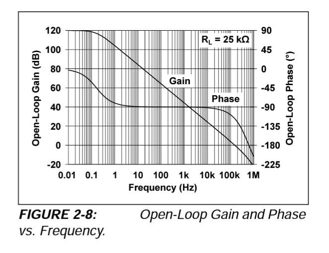
All existing circuits has limit of only 40 Hz. I have an existing circuit based on the schematic in my last message. It has 40 Hz limit too. If you alter the circuit, the most you can push it is 2 kHz because the op-amp MCP607 has that bandwidth at gain of 101 (see above). Also I'm not sure it has the lowest noise.
Also since EMG has same milliVolt range as microphones. I tried to use the LM386 as front end, but the noise may not be good.
When I heard about the E1DA Cosmos with very low noise. I thought of using them to build the audio range bio-potential project. Do you think the low noise and low distortion of the APU for example can make it replace the MCP607?
Do you have any reasoning why audio range frequences and up to 200,000 kHz can't come out of skin? like perhaps the reasoning electrode and skin combination can limit the frequencies acting like low pass filter. Is there such logic?
Of course, most would say we commonly measure up to 100 Hz only. I just want to know the limit of contact measurement. I mean, can you name an object where you can tap a probe into it and measure audio range and not via air conduction (except circuits or radio of course).
solderdude
Grand Contributor
Do you have any reasoning why audio range frequences and up to 200,000 kHz can't come out of skin? like perhaps the reasoning electrode and skin combination can limit the frequencies acting like low pass filter. Is there such logic?
Those frequencies are not likely to be generated by nerves and certainly not muscles.
These are all low frequency, well below the audible range.
What is it that you are attempting to measure ?
The skin itself can probably conduct well into the MHz range but would that really matter if one is only interested in what happens below the skin.
- Thread Starter
- #15
Those frequencies are not likely to be generated by nerves and certainly not muscles.
These are all low frequency, well below the audible range.
What is it that you are attempting to measure ?
The skin itself can probably conduct well into the MHz range but would that really matter if one is only interested in what happens below the skin.
I'm just testing the theories of others that self interacting dark matter and/or monopoles have somehow interacted with the human body as it evolves since from eons and some even claimed to have measured these audio range frequencies and above using biopotential devices.
So I want to attempt to measure it too and debunk it once and for all if I couldn't get any signal. Many in Europe are into this (crackpottery?) and I need to get to the bottom of it.
Let's focus on the circuit. I encountered the AD8232 or "Single-Lead, Heart Rate Monitor Front End" but I read these lines:
"An uncommitted operational amplifier enables the AD8232 to create a three-pole low-pass filter to remove additional noise. The user can select the frequency cutoff of all filters to suit different types of applications." But it seems those frequencies are only up to 100 Hz. Right? See:
I need at a minimum the audio range frequencies or even up to 250 kHz.
So it seems I have to build the front end from scratch or using an INA. Supposed those signals really exist. What noises or factors can make them not visible when measuring for them? For example. Can electrodes and skin somehow act like low pass filter so I need special electrodes. Also If the DC offset of the electrodes used are quite high. It can drown the signal. I read this is why the first stage mustn't be so high gain so you won't magnify the noise too. But others claim CMRR is more important in measuring bio-potential than circuit thermal noises. So I must keep this in mind when trying to look for the dark matter/monopole signal body that couples with so called acupuncture network which is said to be 1/2 the amplitude of resting muscles or baseline. It means it is way smaller than the normal EMG or ECG waveforms. So the circuit must be so low noise as to have very clear resolution of the resting baselines. Do you know of front end chip that can enable to audio range frequencies. I just couldn't find them.
If I couldn't find any signal. I'd debunk all of them at same time. So treat this as exercise of investigation, not futility.
solderdude
Grand Contributor
The biggest question is when you measure up to those frequencies is that, even with a high CMRR of the wires and input, you are not receiving things via the body which are internal. One might need to measure this in RF free chambers (expensive to rent).
When you need a BW of up to 200kHz and need low noise and high gain the design you plan to use will not be suitable.
When you need a BW of up to 200kHz and need low noise and high gain the design you plan to use will not be suitable.
- Thread Starter
- #17
The biggest question is when you measure up to those frequencies is that, even with a high CMRR of the wires and input, you are not receiving things via the body which are internal. One might need to measure this in RF free chambers (expensive to rent).
When you need a BW of up to 200kHz and need low noise and high gain the design you plan to use will not be suitable.
What do you mean by "not receiving things via the body which are internal" and this RF free chamber? Ok. Let me go to the source. It's from Dr. Valerie Hunt. see https://awaken.com/2012/11/valerie-hunt/
I want to repeat her experiments. It is ok if they are just noises that get misunderstood. I need to get to the bottom of it. So let's go back to the 1970s where it all started. This was why i asked elsewhere if analog can detect something that can't be seen in present ADC based instruments. Do you recognize the 1970s technology she used?


A Nasa Engineer designed it for her. In this passage in her book "Infinite Mind":

Don't laugh at her terms like auric field. It was because we still don't have the physics for it if it may all be true and hence using old terms. Modern term can be self interacting dark matter field or sentient coupled monopoles. Or just rubbish I don't mind I just want to understand the truth or if she is fooling around, understood why the technology couldn't have worked. This is why i wrote all this so maybe you could give reasonings why the technology is faulty, etc. if they are that. Thanks.
What do you mean by "not receiving things via the body which are internal" and this RF free chamber? Ok. Let me go to the source. It's from Dr. Valerie Hunt. see https://awaken.com/2012/11/valerie-hunt/
I want to repeat her experiments. It is ok if they are just noises that get misunderstood. I need to get to the bottom of it. So let's go back to the 1970s where it all started. This was why i asked elsewhere if analog can detect something that can't be seen in present ADC based instruments. Do you recognize the 1970s technology she used?
A Nasa Engineer designed it for her. In this passage in her book "Infinite Mind":
Don't laugh at her terms like auric field. It was because we still don't have the physics for it if it may all be true and hence using old terms. Modern term can be self interacting dark matter field or sentient coupled monopoles. Or just rubbish I don't mind I just want to understand the truth or if she is fooling around, understood why the technology couldn't have worked. This is why i wrote all this so maybe you could give reasonings why the technology is faulty, etc. if they are that. Thanks.
The circuitry is the least of your issues. One of the most futile tasks imaginable is to debunk nuts. You can't. Despite experiment after experiment showing no evidence for ESP, dowsing, astrology, faith healing, telekinesis, cable sound, whatever, these continue to be widely held beliefs. "It is useless to attempt to reason a man out of what he was never reasoned into."
- Joined
- Oct 25, 2019
- Messages
- 11,162
- Likes
- 14,861
If only that were true...This is a guitar amp isn't it
Good luck with the debunking attempt (sincerely ) , maybe if you reach an audience like the one here on ASR you can convince others to not join the nuts , the nuts themselves are hardly possible to change . Are you going to publish in some known sceptics journal ?
These are phenomena they have problem measuring at the ICE-cube project fermi lab and cern ?
My small contribution . "New physics" is rarely needed to explain everyday phenomena , it applies on very low levels usually far below the thresholds needed for us on earth. hence why its discovered in nuclear experiments and astrophysics it's only on these scales deviations can be seen .
So you will repeat these measurements with good quality and be able to explain every signal as the noise its probably is and what contribute to that noise ?
RF isolated chamber seem like an idea , the body can be an antenna , you measure with and without rf isolation and can isolate noise pickup from normal electromagnetic sources that's all around us .
The og measurement you quoted seems like the used the natural noise pickup as "tea leaves" and interpreted that somehow ? What they measured can even be place and time dependent ? I mean if they "tuned into" random noise ? I'm not good at this kind of measurement but there may be a method error or several involved ? that's another avenue for debunking ? if you simply can say " you cant measure this way " then you don't need to repeat it all , even if good science is to actually test claims ?
- Status
- Not open for further replies.
Similar threads
- Replies
- 26
- Views
- 3K
- Replies
- 21
- Views
- 839
- Replies
- 16
- Views
- 20K
- Replies
- 4
- Views
- 667