Hi Miki. A point source speaker means that the sound comes from a point. For example,
KEF LS50 (or any KEF using their Uni-Q driver),
Genelec 8351 (or any 1-series Genelec), or even something as large as a
Tannoy Westminster or a
Red Spade PSE-144. Small bookshelf speakers like the
Rogers LS3/5a are not strictly speaking point source, but the drivers are so small and so close together that at normal distances they behave like point source speakers.
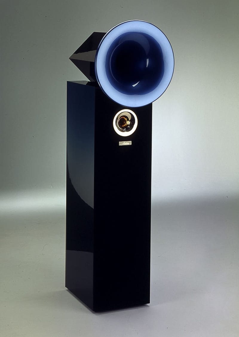
As Audiojester (below) mentions, large multi-driver speakers like mine have a minimum distance where the drivers "converge", although I personally do not know how to define where this distance is in terms of measurements.
Do you know the definition of "converge" in terms of measurements? Help me out here, because I don't know.
I made up my own definition through reasoning that "the convergence point is the distance where the radiation cones of all the drivers mix". Therefore, if you start taking measurements in a straight line backwards from the speaker, the initial measurements closer to the speaker should show massive fluctuations because the drivers have not converged. As you get further away, you reach the convergence point, where any measurements further than this should show the same rate of change. I discussed this a little in
post #32 of this thread where I took progressively further readings from the mic.
If you look carefully at my measurements, the drivers
never converge. The horns and the cabinet
never decay at the same rate, no matter how far I get from the speaker.
I remember looking at this measurement, coming to this realisation, and thinking "I need a beer".
I was complaining to my friend about that Besessen Zwanghaft Audiofil guy and he told me that he is right. I then stared a bit at my living room, and I realized that the width of my room is actually greater than the length of some people's living rooms (6m wide). So yes, I could get away by rotating the system and set it up against the long wall. Besides symmetry, there are other nice benefits, too. e.g. the speakers will be further away from the side walls and I get to look out the big picture window into my garden instead of having the window behind me. It means that the rear wall will be 1m behind the sofa, but I have a washroom, spare bedroom, staircase, etc. which will act as natural diffusers / places for sound to disappear into ... so it will be fine! Getting the speakers far away from the side walls will also help with BACCH.
In preparation for that move, I had to make sure that I could replicate Dr. Uli's tuning that he did for me over a Teamviewer session several months ago. It was the best sounding correction I have ever heard, and all my attempts to replicate it have failed. Tonight, I did a brute force replication by measuring the FR of his correction and setting that as my target. I can already see ASR's brows furrowing over this remark and the knives coming out. But I do what makes me happy, and Dr. Uli's tuning made me happy. The story of that correction is interesting in itself because the result was not what was intended, and I am sure that Dr. Uli himself has not heard this particularly weird looking target curve.
But before I go any further - YES I KNOW WHAT EVERYONE IS THINKING! No need to quote Toole to me, I know what he said about target curves. Just run with me on this one.
View attachment 346614
At the end of the Teamviewer session with Dr. Uli, the verification measurement looked like this (red/green = L/R, brown = target). It sounded great. However, over the months, little changes crept in. The sofa moved forward. Some other furniture was moved around. I made little adjustments to the volume of the tweeter and then adjusted it back. Who knows, maybe something happened to the system. The change in sound was too subtle for me to notice, until I decided to redo the DSP.
Even with the target curve saved on my PC, nothing I did could replicate that sound. In frustration, I repeated the measurements. This is what I saw:
View attachment 346615
Well i'll be a damned monkey's uncle. It looks nothing like the beautiful correction done a few months back. That's not even a "hot" tweeter, because I would expect to see a peak if the tweeter was "hot". Instead, what we get is this weird triangular from 7kHz up. Then it occurred to me ... Dr. Uli did that correction without the sofa in situ. So I removed the sofa and repeated the measurement.
View attachment 346616
By this stage I was struggling to understand what had happened. I tried moving the microphone back by about 1m, and that restored the original appearance of the measurement somewhat. But I had grown to
like this particular sound. It does not even sound too bright, what is most interesting about it are the spatial qualities. It gives the impression of more open-ness, and the ASW is much wider. If I go back to Dr. Uli's target curve, it sounds ... "nice". But this sounds much nicer. That funny looking midrange hump actually adds some richness to the sound, and the top end adds "air" without sounding sibilant or sparkly. There is a kind of ethereal quality.
So out came Acourate. I took the above measurement, applied a lot of smoothing, and used it as a target curve (Acourate users: did you know that you can use any curve as a target curve? Save it as "target.dbl". Skip Room Macro 2 ("Target Curve Design") and proceed directly to Macro 3. Just make sure you adjust the gain of the target and save it, then indicate your new target in Macro 3's dialog box. You can even run different target curves for left and right speakers by ticking the "mono" option and running Macro 3 twice or even 16 different target curves for 16 speakers ... the possibilities are endless). After a full round of corrections, this is the result:
View attachment 346617
It sounds like a more refined version of that odd looking curve I showed earlier. It still has the midrange richness, the ethereal top end, but the image produced is more solid. While I was at it, I replicated Dr. Uli's original target. With Acourate Convolver, I can immediately switch between the two filters:
View attachment 346618
... so now that I know I can replicate that sound, I can now think about moving furniture around to reconfigure the room.

")