
-
WANTED: Happy members who like to discuss audio and other topics related to our interest. Desire to learn and share knowledge of science required. There are many reviews of audio hardware and expert members to help answer your questions. Click here to have your audio equipment measured for free!
- Forums
- Audio, Audio, Audio!
- Amplifiers, Phono preamp, and Analog Audio Review
- Stereo and Multichannel Amplifier Reviews
You are using an out of date browser. It may not display this or other websites correctly.
You should upgrade or use an alternative browser.
You should upgrade or use an alternative browser.
The Truth Pre Amp Review
- Thread starter amirm
- Start date
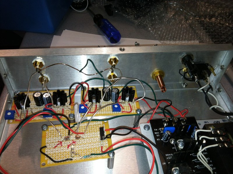
The Truth as tested.
It seems every picture we see presents a different build. This one seems to be mid way in the life, with PCBs for the buffers but not the volume control.
So, this one doesn't have a ground lift, but has an input select switch.
There is solder on the Earth pin of the power socket, but I can't see whether there is a ground lead grounding the chassis. Use of black wire doesn't help. In principle any internal ground lead should be green or yellow-green stripe. It should go to a separate ground point bolted through the chassis.
Direct soldering of mains wires to the power supply is pretty awful. Using a proper connector would have added a few cents to the BOM. Use insulated crimped connectors to connect the the IEC socket, add a proper earth connection and you have a close to spec mains connection. $1 on the BOM and probably a couple of minutes onto the build. It would avoid any exposed mains inside the box. Nasty surprises like exposed pins with mains on them are again, just plain bad manners.
Lack of an on/off switch remains an odd design choice. It leaves the power supply running 7x24x365. Stress on the input stage of the PS from junk on the mains is always there. Given the DC coupled nature of the entire design I wonder if avoiding a power switch is a cheap way of avoiding turn on thumps.
We can see where the crosstalk comes from. There is a pretty basic mistake made with the lead dress of the balance pot. The two channels are twisted together. Perhaps this was done with some idea about resisting interference, but it isn't the correct way of doing it, and the coupling of the two wires is pretty much guaranteed to result in crosstalk.
There are a couple of places where red wires seem to have lost insulation. This is really odd.
There are a few grainy looking solder joints that look less than happy.
There is a length of green wire or insulation lying in the bottom.
restorer-john
Grand Contributor
They are important and hence the reason so many people are able to post them without issue. As I have explained, we use high-speed hosting with SSD drives which is much more costly than hard disk others use. We also don't run ads and have sponsors to pay for such things. Last year I had to double the storage we had and it doubled our hosting costs.
Anyway, I made a change just now. Max file size is 5 megabytes. If you upload a picture with high pixel counts though, the system will resize it down to max of 1,500 by 1,500. This way, there is still a mechanism to keep storage costs low.
That's really good. Often I want to send parts of a service manual or schematics of a decent resolution to people who ask me via PM and I've had to either upload them to google or get a proper email address.
restorer-john
Grand Contributor
I've never seen anything this bad:

Look at how close the bared mains wire is to the chassis mount screw too. OMG!
Whoever built this abomination should be in jail.
Look at how close the bared mains wire is to the chassis mount screw too. OMG!
Whoever built this abomination should be in jail.
- Joined
- Nov 19, 2020
- Messages
- 544
- Likes
- 1,187
I am a layman in terms of electronics but I used to be a lawyer and I guess (at least in my country), the chance of facing a criminal court in case this circuit fails with lethal consequences is real.I've never seen anything this bad:
View attachment 135477
Look at how close the bared mains wire is to the chassis mount screw too. OMG!
Whoever built this abomination should be in jail.
solderdude
Grand Contributor
It's not 'good practice' for sure.
Good practice would have been: using the appropriate (crimp) connector, using stranded wire, at least cover parts that can be 'live' when touched and maybe even use the framed version of this SMPS (would lower stray EM fields as well).
In his defense, the solid wires have been kind of wrapped before soldering (soddering, sautering whatever we call it). As we cannot see how the stripping was done there is always a chance of the wire breaking at the stripping point when the wire was nicked.
Facing criminal court for this would only happen when someone actually died or was injured while touching live parts. Seeing the safety ground is connected (I can see some solder but not what's connected to it) that would have to be when someone opens it up while connected to mains.
In such case the pre-amp cannot be used anyway as the LDR's are not covered.
And... the balance pot is still in the audio path despite Ed believing/claiming it is not.
But yes ... it appears to be a safety hazard when opening it up and would have cost nearly nothing to at least make the mains part safe.
Ed also could have decided to buy the SMPS in a metal frame but that would have made theprofit (compensation for his time) slightly less.
'Sauteringdoood'
Good practice would have been: using the appropriate (crimp) connector, using stranded wire, at least cover parts that can be 'live' when touched and maybe even use the framed version of this SMPS (would lower stray EM fields as well).
In his defense, the solid wires have been kind of wrapped before soldering (soddering, sautering whatever we call it). As we cannot see how the stripping was done there is always a chance of the wire breaking at the stripping point when the wire was nicked.
Facing criminal court for this would only happen when someone actually died or was injured while touching live parts. Seeing the safety ground is connected (I can see some solder but not what's connected to it) that would have to be when someone opens it up while connected to mains.
In such case the pre-amp cannot be used anyway as the LDR's are not covered.
And... the balance pot is still in the audio path despite Ed believing/claiming it is not.
But yes ... it appears to be a safety hazard when opening it up and would have cost nearly nothing to at least make the mains part safe.
Ed also could have decided to buy the SMPS in a metal frame but that would have made the
'Sauteringdoood'
AudioSceptic
Major Contributor
Don't hold back. Say what you really think!I've never seen anything this bad:
View attachment 135477
Look at how close the bared mains wire is to the chassis mount screw too. OMG!
Whoever built this abomination should be in jail.
")
No really, I meant artistic quality. It was meant as a joke...ok, so it's this. Silly me, I thought it meant quality of content.
View attachment 135330
mhardy6647
Grand Contributor
- Joined
- Dec 12, 2019
- Messages
- 11,470
- Likes
- 24,919
Now all y'all gots me wonderin' about the quality of my avatar!
I quite like it, bein' a reckless, feckless kind o'feller.
but...
if DANGER PART doesn't pass muster -- I could reanimate (so to speak) my alter ego, Anxious Box.

I always felt kinda bad for Anxious Box. He looks like he needs some cardboard Xanax or somethin'...
PS @amirm Thanks for upping the file upload size! Very nice of you. I really do need to be come a contributing member (in the fiscal sense) -- given the amount of drivel I have infected your servers with in the past year or so...
I quite like it, bein' a reckless, feckless kind o'feller.
but...
if DANGER PART doesn't pass muster -- I could reanimate (so to speak) my alter ego, Anxious Box.
I always felt kinda bad for Anxious Box. He looks like he needs some cardboard Xanax or somethin'...
PS @amirm Thanks for upping the file upload size! Very nice of you. I really do need to be come a contributing member (in the fiscal sense) -- given the amount of drivel I have infected your servers with in the past year or so...
Bob from Florida
Major Contributor
- Joined
- Aug 20, 2020
- Messages
- 1,319
- Likes
- 1,221
Now all y'all gots me wonderin' about the quality of my avatar!
I quite like it, bein' a reckless, feckless kind o'feller.
but...
if DANGER PART doesn't pass muster -- I could reanimate (so to speak) my alter ego, Anxious Box.
View attachment 135528
I always felt kinda bad for Anxious Box. He looks like he needs some cardboard Xanax or somethin'...
PS @amirm Thanks for upping the file upload size! Very nice of you. I really do need to be come a contributing member (in the fiscal sense) -- given the amount of drivel I have infected your servers with in the past year or so...
Just be sure to add a safety ground wire - in the right color - to your avatar and all will be well. Maybe.....
In his defense, the solid wires have been kind of wrapped before soldering
No defense should be expressed in such case as shown.
D
Deleted member 26571
Guest
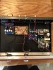
Here's another one of these masterpieces.
Edit: I think it's really important to only use two screws on each board. The resulting flexibility imparts a naturally-warm resonance to the sound.
restorer-john
Grand Contributor
One can only imagine what the underside of those boards looks like...
MakeMineVinyl
Major Contributor
I suppose that ground buss wire is precisely bent so it is tuned to impart the exact magical sound quality this stunning preamp is capable of. Oh the genius of it all, if only I could comprehend.
Here's another one of these masterpieces.
Edit: I think it's really important to only use two screws on each board. The resulting flexibility imparts a naturally-warm resonance to the sound.
restorer-john
Grand Contributor
I suppose that ground buss wire is precisely bent so it is tuned to impart the exact magical sound quality this stunning preamp is capable of.
I think it's left over from this prototype, his highly sophisticated electronic game that never went to market.
mhardy6647
Grand Contributor
- Joined
- Dec 12, 2019
- Messages
- 11,470
- Likes
- 24,919
<image snipped, see below>
Here's another one of these masterpieces.
Edit: I think it's really important to only use two screws on each board. The resulting flexibility imparts a naturally-warm resonance to the sound.
I think it's left over from this prototype, his highly sophisticated electronic game that never went to market.
View attachment 135620
Looks like a theremin that has been tuned to make it easier to play a chromatic scale(?)
restorer-john
Grand Contributor
Seriously, if these pictures are representative of the Truth Preamps out in the wild, built by this guy, then we surely have a duty to report these things as not being of merchantable quality, not fit for purpose and/or sale and likely dangerous or unsafe.
They are charging well over US$1000 for this piece of junk.
They are charging well over US$1000 for this piece of junk.
JSmith
Master Contributor
If this is the truth... I don't want to know or handle the truth.you can't handle the truth

JSmith
Similar threads
- Poll
- Replies
- 307
- Views
- 33K
- Replies
- 455
- Views
- 111K
- Replies
- 360
- Views
- 76K
- Poll
- Replies
- 146
- Views
- 25K
- Replies
- 585
- Views
- 59K