• WANTED: Happy members who like to discuss audio and other topics related to our interest. Desire to learn and share knowledge of science required. There are many reviews of audio hardware and expert members to help answer your questions. Click here to have your audio equipment measured for free!

Using two microphones to remove room modes from bass measurements

TheBatsEar

Major Contributor
Forum Donor
Joined
Jun 16, 2020
Messages
3,180
Likes
5,162
Location
Germany
I found this article and wonder if anyone has experience with this technique of making quasi anechoic measurements in regular rooms down to 10Hz.


The microphone array costs 700€ and here is a snippet of what i can do:
1700950869870.png


This is what the main attraction looks like:
DSC06922-1024x664.jpg


Contents of the package:
1700951123700.png


You also need some software (REW for example) and a PC to run it on and a good USB interface, like a Scarlet 2i2.

More links:
 

Blumlein 88

Grand Contributor
Forum Donor
Joined
Feb 23, 2016
Messages
20,771
Likes
37,636
I've had the idea of doing something like this, but never really did any work on it. Didn't know others had looked into it, but not surprised someone did.

Seems like something the Umik X from miniDSP could be adapted to do automatically if they wanted to make it so.
 

dominikz

Addicted to Fun and Learning
Forum Donor
Joined
Oct 10, 2020
Messages
806
Likes
2,638
Looks really interesting but given the close measurement distance (5-10cm) wouldn't the results still require some baffle step correction and manual summation of additional driver/port responses?
If that is true, what would be the benefit of this method compared to the usual nearfield (<1cm) measurement methods?
Also, measurement distance seems to be still too close to the speaker to allow polar response measurements.
Any thoughts?
 

alex-z

Addicted to Fun and Learning
Joined
Feb 19, 2021
Messages
914
Likes
1,694
Location
Canada
Seems to me you could do the same thing by moving a single mic and summing the measurements manually.

Pretty niche application though, you could just do a ground plane measurement outdoors and splice that. Designing a speaker indoors is like playing basketball in a bowling alley.
 
OP
TheBatsEar

TheBatsEar

Major Contributor
Forum Donor
Joined
Jun 16, 2020
Messages
3,180
Likes
5,162
Location
Germany
If someone is able to thoroughly evaluate the hardware and methods, i can purchase and ship a testing unit within Europe.
Send a PM if you think that is you.

Edit: @amirm is getting one for evaluation from the company.

baffle step correction
Do we even care once the wavelength approaches tens of meters? The device is accurate up to 1kHz, wich in air has a wavelength of 34.32cm. I suspect this is when things get out of whack. It also means your front baffle is ~68cm wide, a monster speaker! :oops:

Seems to me you could do the same thing by moving a single mic and summing the measurements manually.
You would still have the room in your measurements, just averaged across many points.

This device has two points of measurements. One is closer, thus louder, with less room influence. The other is further away, less loud, with more room influence. From that, if you know the precise distance of the microphones, you can then somehow delete the room influence and come to a pure speaker measurement.

That said, i might be wrong, because i haven't fully understood what is done yet, i lack the first principles knowledge of the physics it seems.
 
Last edited:
OP
TheBatsEar

TheBatsEar

Major Contributor
Forum Donor
Joined
Jun 16, 2020
Messages
3,180
Likes
5,162
Location
Germany
Designing a speaker indoors is like playing basketball in a bowling alley.
That's what she said the guys at Klippel in Germany said.;)
And yet they did what nobody else did.
 

Kaameelis

Member
Joined
Jan 1, 2022
Messages
31
Likes
3
This compensation can be done also in software when 2 mic signals are recorded and result can be feed to REW as file. Basically no need for special compensation hardware but then real time measurement is not possible.
 

ctrl

Major Contributor
Forum Donor
Joined
Jan 24, 2020
Messages
1,633
Likes
6,241
Location
.de, DE, DEU
technique of making quasi anechoic measurements in regular rooms down to 10Hz.
The method has no real advantage in correctly measuring the frequency response of loudspeakers, only when measuring drivers in an infinite baffle - see details below.

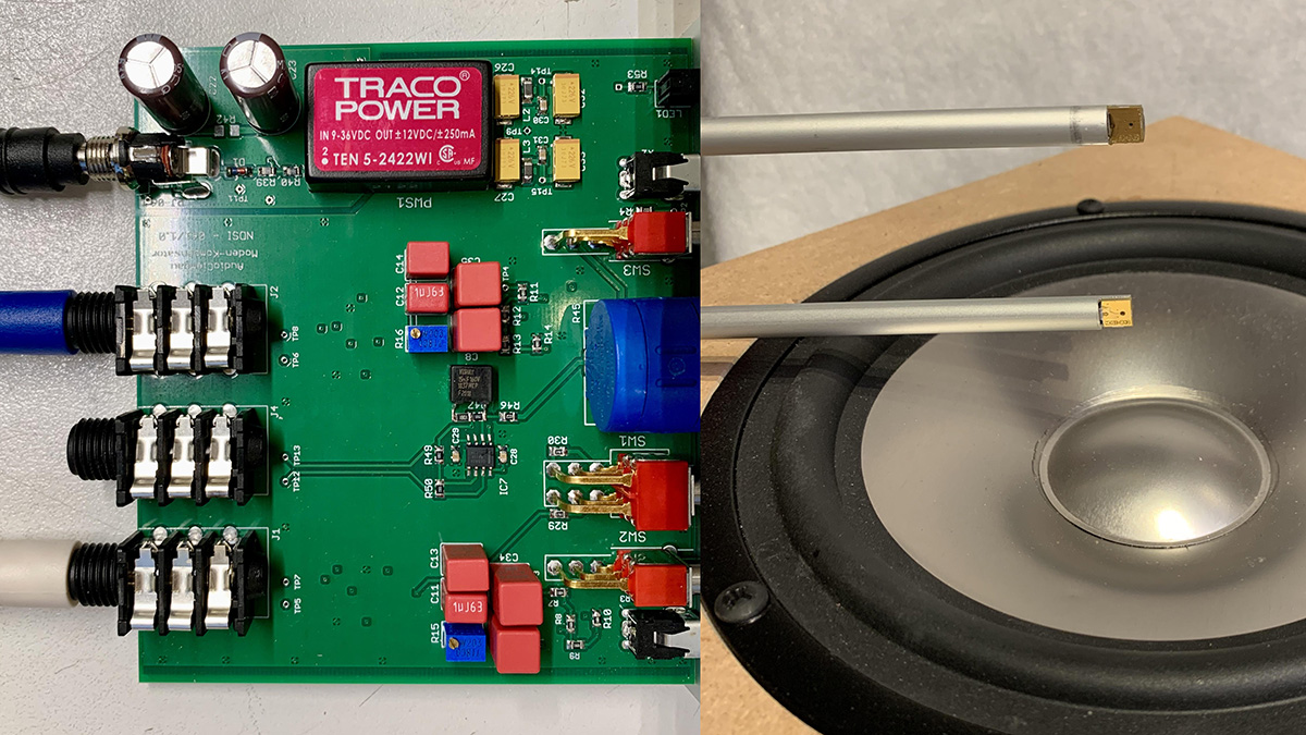
This method has small advantages over a near-field measurement of a driver at a distance of <0.01m from the dust cap, as at a distance of 0.05m (first mic), for example, possible resonances due to the driver surround would have a slightly greater influence on the overall frequency response (thus would be more realistic).

There is a further small advantage if harmonic distortion in the near field is also to be measured during the FR measurement. With only one microphone, the measurement distance must be significantly reduced in order to suppress room influences similarly well - for example to 0.01m, but this means a 14dB higher sound pressure level at the microphone (as a result, the distortion of the mic influence the distortion measurements of the driver earlier).

Do we even care once the wavelength approaches tens of meters? The device is accurate up to 1kHz, wich in air has a wavelength of 34.32cm. I suspect this is when things get out of whack. It also means your front baffle is ~68cm wide, a monster speaker!
To determine the entire frequency response of a loudspeaker from 20-20000Hz accurately, this method has practically no advantages over the usual method of near-field measurement at the driver (<0.01m), baffle step correction and subsequent merging of near-field measurement and gated measurement of the speaker - on the contrary, frequency response deviations occur even earlier because of the 0.05-0.1m measuring distance.

The usual baffle step correction takes a two-dimensional model of the baffle (height and width) and simulates its influence on the frequency response.
The depth of the cabinet is not taken into account.

This has consequences for the validity of the simulation in relation to the upper frequency limit.
Furthermore, when applying the baffle step correction, the signal to be corrected must not contain any baffle influences (otherwise influences would be applied several times). Therefore, the near-field measurement should be performed as close as possible to the dust cap in order to minimize the influence of the DUT (dimension of the DUT ).
The rule of thumb is: measuring distance <0.11*"largest dimension DUT" delivers FR with error <1dB.

Upper frequency limit for correct performed near field measurements dependent on source size:
1701008229711.png
Source: Arta Handbook

A measurement distance of 0.05-0.1m, as used in the "double microphone method", already contains significant DUT influences (depending on the dimension of the DUT). Only at very low frequencies do these play only a minor role.
In order to be able to apply a baffle step correction without large errors, the frequency at which the near-field measurement is combined with the gated measurement must be set particularly low when using the "double microphone method" near field measurements, so one can't use in no way the "accurate FR" up to 1kHz of the "double microphone method".
 

Blumlein 88

Grand Contributor
Forum Donor
Joined
Feb 23, 2016
Messages
20,771
Likes
37,636
I was considering trying it with a two omni pencil mikes. Decided it was easier to simulate to see if it held merit.

So I created a log sweep in Audacity. Then made a copy -6 db in level to simulate the 2nd mike. Then applied an EQ like room modes to both signals. Then applied that EQ a second time to the lower level signal from the 2nd mike. The idea being the signal is lower and the room modes twice as high relatively speaking. Inverted the 2nd mike signal, and subtracted or mixed the two. Done this way the difference over-compensates. It needs about a 3 db reduction in the 2nd mike signal to come close to straightening this out. Then when the two are mixed it does result in much closer to the flat original response. I didn't need any filters and there is no time difference in the two microphone signals this way. You do need a slight -3 db per octave filter for better results. Or use a linear rather than a log sweep. I think part of their filters are for this too.

So the idea in principal can certainly work.
 

NTK

Major Contributor
Forum Donor
Joined
Aug 11, 2019
Messages
2,716
Likes
6,007
Location
US East
I have only very quickly skimmed the AudioXpress article. Can this be very different from or perform significantly better than a standard 2-microphone endfire beamformer? If it is the same (or similar), the directivity of the 2-mic array with omni mics is equal to that of a cardioid. Then, why not just use a cardioid mic to measure?


ctrl

Major Contributor
Forum Donor
Joined
Jan 24, 2020
Messages
1,633
Likes
6,241
Location
.de, DE, DEU
I have only very quickly skimmed the AudioXpress article. Can this be very different from or perform significantly better than a standard 2-microphone endfire beamformer? If it is the same (or similar), the directivity of the 2-mic array with omni mics is equal to that of a cardioid. Then, why not just use a cardioid mic to measure?
With a cardioid microphone, there is little or no distance between the mic sources (front and rear diaphragm or perhaps two mutually bonded mic capsules).

The trick with the "double mic" method is to say that noise and room reflections are practically identical for mic1 and mic2 (as long as the distance between mic1 and 2 is not to far away), but by doubling the distance to the sound source (from 0.05m to 0.1m) the SPL of the source drops by 6dB at mic2.

If the phase of mic2 is inverted and summed with mic1, noise is reduced and room reflections are canceled out (as they are identical for low-middle frequencies), but the frequency response of the sound source at mic1 is only lowered by a few dB.
This produces the reflection-free FR of the sound source - If I have understood the principle correctly.
 
Last edited:

amirm

Founder/Admin
Staff Member
CFO (Chief Fun Officer)
Joined
Feb 13, 2016
Messages
44,679
Likes
241,141
Location
Seattle Area
FYI the company approached me about sending me a unit to test. I expressed to him the issues around baffle step compensation. We went back and forth a bit but I don't remember how it ended.
 

mwmkravchenko

Active Member
Joined
Nov 20, 2018
Messages
181
Likes
197
Location
Perth Ontario
With a cardioid microphone, there is little or no distance between the mic sources (front and rear diaphragm or perhaps two mutually bonded mic capsules).

The trick with the "double mic" method is to say that noise and room reflections are practically identical for mic1 and mic2 (as long as the distance between mic1 and 2 is not to far away), but by doubling the distance to the sound source (from 0.05m to 0.1m) the SPL of the source drops by 6dB at mic2.

If the phase of mic2 is inverted and summed with mic1, noise is reduced and room reflections are canceled out (as they are identical for low-middle frequencies), but the frequency response of the sound source at mic1 is only lowered by a few dB.
This produces the reflection-free FR of the sound source - If I have understood the principle correctly.
If I remember correctly this is done with the Smith&Larson Speakertester Pro, and perhaps ARTA.
 

AudioChiemgau

New Member
Joined
Feb 7, 2021
Messages
4
Likes
12
I found this article and wonder if anyone has experience with this technique of making quasi anechoic measurements in regular rooms down to 10Hz.


The microphone array costs 700€ and here is a snippet of what i can do:
View attachment 329353

This is what the main attraction looks like:
DSC06922-1024x664.jpg


Contents of the package:
View attachment 329355

You also need some software (REW for example) and a PC to run it on and a good USB interface, like a Scarlet 2i2.

More links:
This is Reinhold Lutz from AudioChiemgau. In case you are interested in a detailed description of the physics behind this measurement technique, have a look to our webpage www.AudioChiemgau.de -> ModeCompensator -> scroll to the bottom and you will find a link to the PDF "Background ... " I attach the PDF, but I am not sure this works.

We have been sold out, but I will send a ModeCompensator to Amir in the next days. The ModeCompensator is intended to measure the frequency response and the harmonic distortions of the sound pressure in the near field (up to 20 cm distance in a standard lab). You will miss the baffle step of the enclosure, but you will for the first time in your life measure without room modes down to 10 Hz with a 0.1 Hz frequency resolution. That is what the ModeCompensator was developed for.
 

Attachments

  • ModeCompensator Background.pdf
    1.2 MB · Views: 51

dominikz

Addicted to Fun and Learning
Forum Donor
Joined
Oct 10, 2020
Messages
806
Likes
2,638
This is Reinhold Lutz from AudioChiemgau. In case you are interested in a detailed description of the physics behind this measurement technique, have a look to our webpage www.AudioChiemgau.de -> ModeCompensator -> scroll to the bottom and you will find a link to the PDF "Background ... " I attach the PDF, but I am not sure this works.

We have been sold out, but I will send a ModeCompensator to Amir in the next days. The ModeCompensator is intended to measure the frequency response and the harmonic distortions of the sound pressure in the near field (up to 20 cm distance in a standard lab). You will miss the baffle step of the enclosure, but you will for the first time in your life measure without room modes down to 10 Hz with a 0.1 Hz frequency resolution. That is what the ModeCompensator was developed for.
Welcome dr. Lutz!

The system looks really interesting!

Thanks for confirming baffle step isn't included in the measured response. I've read the paper but still have a few questions, hope you won't mind!

Since this in effect seems to be a driver nearfield measurement, would I be correct in assuming that in bass-reflex boxes we'd still need to separately measure the woofer and the port, and then sum them manually (weighted based on their respective radiation surface)?
Similarly for multi-driver boxes, I assume we'd need to measure each driver separately and then sum the responses accordingly, right?

Further, is there any way we could use this system to make more precise off-axis radiation measurements (e.g. to generate a full CEA2034 spinorama)?

Lastly, the single-microphone ultra-nearfield driver measurements (e.g. <1cm from the dustcap) were used traditionally for the same purpose, with IMHO respectable results. However, as far as I understand, comparable benefits of your method would be:
- More accurate response shape due to somewhat higher measurement distance
- Even higher resistance to ambient noise and room modes
- More precise distortion measurement
- Valid to a higher frequency (up to 1kHz with 5cm measurement distance)
Would you agree, and did I miss something?

Thanks a lot in advance!
 

AudioChiemgau

New Member
Joined
Feb 7, 2021
Messages
4
Likes
12
-> would I be correct in assuming that in bass-reflex boxes we'd still need to separately measure the woofer and the port, and then sum them manually (weighted based on their respective radiation surface)?
Correct.

-> is there any way we could use this system to make more precise off-axis radiation measurements (e.g. to generate a full CEA2034 spinorama)?
The physics behind that system relays on 1) One-over-Distance law (i.e. a spherical wave) and 2) on the same sound pressure of modes at both microphones.
In theory you could place the first microphone at 1 Meter and the second at 2 Meter, however, 1) The SNR would somewhat degrade and 2) the probability of the same mode and environmental sound pressure at both microphones would be low. In other words you would need a large, or more or less anechoic room. This is not what the ModeCompensator was developed for.

-> comparable benefits of your method would be ...
All above listed advantages are correct.
Have a look to the SPL as function of distance in the 'Background' paper: The sound pressure is 1) constant very close to the membrane and 2) you have significant distortions due to the doppler effect (independent from the measurement distance) and the nonlinear amplitude modulation (dependent on the measurement distance) the moving membrane generates. Therefore we recommend >=5 cm .. <=15 cm measurement distance for the first microphone. Ultra-nearfield driver measurements are not suitable for harmonic distortion measurements.

My simple opinion: When you want to measure the sound pressure frequency response and its harmonic distortions in a standard lab down to 10 Hz with 0.1 Hz resolution you need the ModeCompensator. Alternatively you need the Cube of B&O, or a huge anechoic chamber, which does not exist in Europe, or you go outdoor.
When the Spinorama is the target I would recommend e.g. Klippel.
 

dominikz

Addicted to Fun and Learning
Forum Donor
Joined
Oct 10, 2020
Messages
806
Likes
2,638
-> would I be correct in assuming that in bass-reflex boxes we'd still need to separately measure the woofer and the port, and then sum them manually (weighted based on their respective radiation surface)?
Correct.

-> is there any way we could use this system to make more precise off-axis radiation measurements (e.g. to generate a full CEA2034 spinorama)?
The physics behind that system relays on 1) One-over-Distance law (i.e. a spherical wave) and 2) on the same sound pressure of modes at both microphones.
In theory you could place the first microphone at 1 Meter and the second at 2 Meter, however, 1) The SNR would somewhat degrade and 2) the probability of the same mode and environmental sound pressure at both microphones would be low. In other words you would need a large, or more or less anechoic room. This is not what the ModeCompensator was developed for.

-> comparable benefits of your method would be ...
All above listed advantages are correct.
Have a look to the SPL as function of distance in the 'Background' paper: The sound pressure is 1) constant very close to the membrane and 2) you have significant distortions due to the doppler effect (independent from the measurement distance) and the nonlinear amplitude modulation (dependent on the measurement distance) the moving membrane generates. Therefore we recommend >=5 cm .. <=15 cm measurement distance for the first microphone. Ultra-nearfield driver measurements are not suitable for harmonic distortion measurements.

My simple opinion: When you want to measure the sound pressure frequency response and its harmonic distortions in a standard lab down to 10 Hz with 0.1 Hz resolution you need the ModeCompensator. Alternatively you need the Cube of B&O, or a huge anechoic chamber, which does not exist in Europe, or you go outdoor.
When the Spinorama is the target I would recommend e.g. Klippel.
Thanks a lot for the detailed answer, much appreciated! :)
 
OP
TheBatsEar

TheBatsEar

Major Contributor
Forum Donor
Joined
Jun 16, 2020
Messages
3,180
Likes
5,162
Location
Germany
OP
TheBatsEar

TheBatsEar

Major Contributor
Forum Donor
Joined
Jun 16, 2020
Messages
3,180
Likes
5,162
Location
Germany
Top Bottom