• WANTED: Happy members who like to discuss audio and other topics related to our interest. Desire to learn and share knowledge of science required. There are many reviews of audio hardware and expert members to help answer your questions. Click here to have your audio equipment measured for free!

Topping PA5 Review (Amplifier)

nsfgp

Active Member
Joined
Dec 27, 2020
Messages
200
Likes
185
None of those is a truly balanced conversion...

A balanced signal has 2 equal signals in opposing polarities ....
Want to ask some more. There are gears with balanced output that are "Impedance-Balanced" (some called it semi-balanced) with signal driving one leg only(hot); the other leg(cold) at 0V(ground). Someone on this thread mentioned using his Audient audio interface that is impedance-balanced only with his PA5 for months already and still working.

Is there evidence that using such gear will cause issue with the PA5?? Not seeing any warning from Topping about using such "balanced" gear with PA5.
Mainly want to focus on the reliability side of things. Thanks.
 

nagster

Senior Member
Joined
Jan 24, 2021
Messages
368
Likes
602
None of those is a truly balanced conversion...

A balanced signal has 2 equal signals in opposing polarities ....

View attachment 201010
From what we've gathered so far the PA5 does not have the facility to handle any kind of cable trickery. It actually needs both active signals to operate properly.

I've included the PDF schematic for a single ended to true balanced converter... the schematic has been built and tested and works quite well. Distortion is below my measuring ability, frequency response runs 2 hz to over 100khz, max output is the supply -2 volts. The gain pot gives plus or minus 10db from centre so you can level match your inputs.

View attachment 201056


There are ready made options you can order online, as well.
I think your proposal is also one of the candidates.
Generally, there is no difference even if one side is grounded,
The PA5 behaves strangely, so the maximum output increases by 15% (4ohm load) when both positive and negative signals are input.
The THD+N ratio is lost by 0.0001% when positive or negative is grounded.
That's all the confirmed differences.
With a transformer or active converter, THD+N will actually be lost even more.
But the PA5 may have more secrets...
 
D

Deleted member 46664

Guest
Want to ask some more. There are gears with balanced output that are "Impedance-Balanced" (some called it semi-balanced) with signal driving one leg only(hot); the other leg(cold) at 0V(ground). Someone on this thread mentioned using his Audient audio interface that is impedance-balanced only with his PA5 for months already and still working.

Is there evidence that using such gear will cause issue with the PA5?? Not seeing any warning from Topping about using such "balanced" gear with PA5.
Mainly want to focus on the reliability side of things. Thanks.

If my hunch is correct, grounding or deadheading either balanced lead shuts down one side of the BTL output.
If I'm wrong, then I have no idea what they've done and, so far, no schematics...

So at this moment the best answer is ... We don't actually know.

The actual test is pretty simple ...
Get voltmeters or a scope on the two speaker posts for one channel measuring AC against ground.
Plug in a TRS plug for that channel
Feed a single audio signal into one of the two signal pins.
See what happens.

If only one side of the outputs is active, we have our answer.
If both are active... we also have our answer.
 
Last edited by a moderator:

antcollinet

Master Contributor
Forum Donor
Joined
Sep 4, 2021
Messages
7,747
Likes
13,082
Location
UK/Cheshire
If my hunch is correct, grounding or deadheading either balanced lead shuts down one side of the BTL output.
If I'm wrong, then I have no idea what they've done and, so far, no schematics...

So at this moment the best answer is ... We don't actually know.

The actual test is pretty simple ...
Get voltmeters or a scope on the two speaker posts for one channel measuring AC against ground.
Plug in a TRS plug for that channel
Feed a single audio signal into one of the two signal pins.
See what happens.

If only one side of the outputs is active, we have our answer.
If both are active... we also have our answer.
Thing is - if that was the case, you could expect the peak power to be a quarter of rated. But it reaches about 3/4 of rated power, according to the power/distortion charts shown above.

And the scope plots (if i've interpreted correctly) show only a small voltage difference between the two speaker terminals. (3.9 vs 5.3 volts)
 
D

Deleted member 46664

Guest
Thing is - if that was the case, you could expect the peak power to be a quarter of rated. But it reaches about 3/4 of rated power, according to the power/distortion charts shown above.

And the scope plots (if i've interpreted correctly) show only a small voltage difference between the two speaker terminals. (3.9 vs 5.3 volts)

We want to look at the two sides of the BTL output separately.
Okay ... two voltmeters... on their AC scale one on the red speaker terminal to ground the other on the black speaker terminal to ground.
TRS plug on the input ... feed in a test tone on the TIP connector leaving the RING connector open.

A) If it is fully balanced and can't do single ended ... only one voltmeter will display an AC voltage.
b) If it is correctly designed... both should show the same AC voltage.

That is ... it should not matter if you have it hooked up single ended or balanced... the output should be the same!
 

antcollinet

Master Contributor
Forum Donor
Joined
Sep 4, 2021
Messages
7,747
Likes
13,082
Location
UK/Cheshire
We want to look at the two sides of the BTL output separately.
Okay ... two voltmeters... on their AC scale one on the red speaker terminal to ground the other on the black speaker terminal to ground.
TRS plug on the input ... feed in a test tone on the TIP connector leaving the RING connector open.

A) If it is fully balanced and can't do single ended ... only one voltmeter will display an AC voltage.
b) If it is correctly designed... both should show the same AC voltage.

That is ... it should not matter if you have it hooked up single ended or balanced... the output should be the same!
And in the test carried out - as far as I can see from the scope traces. Neither is the case. When you put a signal on one input and 0V on the other. The output is the same total voltage (just over 9V differential) but "partly unbalanced".

Suggests there is a rebalancing circuit, but it doesn't perfectly rebalance.
 

Keened

Senior Member
Forum Donor
Joined
Nov 2, 2021
Messages
329
Likes
219
And in the test carried out - as far as I can see from the scope traces. Neither is the case. When you put a signal on one input and 0V on the other. The output is the same total voltage (just over 9V differential) but "partly unbalanced".

Suggests there is a rebalancing circuit, but it doesn't perfectly rebalance.
Hmm, it's also odd that they have a 38v input for a 32v chip. Maybe they do a single end conversion somewhere in the chain that is amped separately (Class A?) as well as being differentially amplified. It would explain the additional voltage requirement and the heat even at idle.

So balanced in -> Differential amplification on both -> Convert to Single End -> Final amplification that bumps the output voltage to meet the threshold -> sent back out balanced ?

Edit: Or maybe the Class A comes first on all incoming signals to raise them to the threshold at which the differential amplification can work best. Older chip Class D have issues with power and linearity right? Differential amplification also has issues with noise, so if you use Class A to bring it up first you can have both parts work in an easier range.
 
D

Deleted member 46664

Guest
And in the test carried out - as far as I can see from the scope traces. Neither is the case. When you put a signal on one input and 0V on the other. The output is the same total voltage (just over 9V differential) but "partly unbalanced".

Suggests there is a rebalancing circuit, but it doesn't perfectly rebalance.

It would have been nice if those photos were marked so we knew which ones were taking from the input and which were from the outputs... In any case what I saw there was inconclusive at best.
 
D

Deleted member 46664

Guest
Hmm, it's also odd that they have a 38v input for a 32v chip. Maybe they do a single end conversion somewhere in the chain that is amped separately (Class A?) as well as being differentially amplified. It would explain the additional voltage requirement and the heat even at idle.

It is a single chip Class-D amplifier. The heat at idle is probably because the chip is frying.

So balanced in -> Differential amplification on both -> Convert to Single End -> Final amplification that bumps the output voltage to meet the threshold -> sent back out balanced ?

The right way...

index.php

The wrong way...

index.php
 
Last edited by a moderator:

pjug

Major Contributor
Forum Donor
Joined
Feb 2, 2019
Messages
1,776
Likes
1,562
Hmm, it's also odd that they have a 38v input for a 32v chip.
The TI amp is rated for 38V max under recommended operating conditions. Absolute maximum is 50V so it can handle some ripple or whatever. It doesn't seem to me that Topping is doing anything wrong by operating at 38V, assuming the power supply voltage is not off the mark.
 

nagster

Senior Member
Joined
Jan 24, 2021
Messages
368
Likes
602
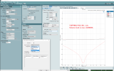
PA5 CMRR
Volume knob is max. (gain 19.1dB)
I also measured Rch and IN2, but I will not post it because it was a difference in measurement error.
pa5_cmrr_full.png
 

Attachments

  • pa5_cmrr_full_ref.png
    pa5_cmrr_full_ref.png
    177.7 KB · Views: 99
  • pa5_cmrr_full_graph.png
    pa5_cmrr_full_graph.png
    173.1 KB · Views: 95
  • Like
Reactions: pma

nagster

Senior Member
Joined
Jan 24, 2021
Messages
368
Likes
602
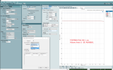
PA5 CMRR
Volume knob is -20. (gain -0.9dB)

@DualTriode
I may have seen a post that you got a PA5.
If that's right, join us here in your spare time.
 

Attachments

  • pa5_cmrr_-20_ref.png
    pa5_cmrr_-20_ref.png
    177.1 KB · Views: 91
  • pa5_cmrr_-20_graph.png
    pa5_cmrr_-20_graph.png
    163.2 KB · Views: 93
  • Like
Reactions: pma
D

Deleted member 46664

Guest
The TI amp is rated for 38V max under recommended operating conditions. Absolute maximum is 50V so it can handle some ripple or whatever. It doesn't seem to me that Topping is doing anything wrong by operating at 38V, assuming the power supply voltage is not off the mark.

If you want to build something that lasts and gives consistent performance you don't push it to within an inch of killing itself.
The "typical" voltage for the TPA3251 is 36 volts... 32 is a commonly available power supply... so use 32.

It's not like it goes from LOUD to whisper. You won't hear the difference, it's only costing you about 3 watts, if that.

So you design for longevity, as any sensible designer would.

It might also be helpful to look at the voltage ratings on some of the other parts ... Bulk supply capacitors in particular, but also regulators and op-amps.
 
D

Deleted member 46664

Guest
PA5 CMRR
Volume knob is -20. (gain -0.9dB)
These are very impressive measurements ... however they do not answer the original question all those pages ago...

Let me rephrase it again ....
If I feed in a single ended signal on the TIP of the left channel, does one side of the left channel's BTL output pair shut down --or-- do both sides continue to operate normally?

And no... audio precision cmrr graphs will not answer the question.
 

antcollinet

Master Contributor
Forum Donor
Joined
Sep 4, 2021
Messages
7,747
Likes
13,082
Location
UK/Cheshire
It would have been nice if those photos were marked so we knew which ones were taking from the input and which were from the outputs... In any case what I saw there was inconclusive at best.
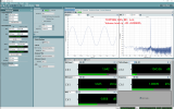
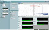
It's inferrable from the voltages. @nagster (Please confirm or otherwise my interpretation) is inputting a 1V signal in both cases - once hot and cold 1/2V and Single ended 1V two ways, once to the hot signal and once to the cold. (The scope traces are labelled)

In both cases, the result is an (aprox) 9V differential output (Corresponds to the 19 ish dB gain of the amp). With the balanced signal, the output is symmetrical, with 4.6V on each output. With the unbalanced signal, it shows asymmetric 5.3V and 3.9V. Adding to the same output voltage.

The reduced max power with the unbalanced signal will result from the higher of the two voltages clipping earlier than the fully balanced voltages. Which is why it is only a 25% or so power reduction.

How/why this happens is anyones guess, but my conclusion is there must be some form of re-balancing before the BTL amplification, and that the amp actually works sort of OK from an unbalanced signal if you can put up with the peak power limitation of about 1dB.


For future reference, scope traces are in this post:

 
Last edited:

hyperknot

Active Member
Joined
Aug 17, 2019
Messages
260
Likes
166
Is there a statement about the warranty errors and which revision is fixed? I've waited to buy this until the initial issues are resolved, but I'd like to buy one which is definitely from a fixed batch already.
 

DualTriode

Addicted to Fun and Learning
Joined
Oct 24, 2019
Messages
903
Likes
595
PA5 CMRR
Volume knob is -20. (gain -0.9dB)

@DualTriode
I may have seen a post that you got a PA5.
If that's right, join us here in your spare time.

Hello,

Yes I did purchase a PA5 amplifier.

I also purchased a AP AUX 0040 AES17 filter. The filter has not shipped yet.

When the filter arrives I will post some test plots of the PA5 amplifier.

Thanks DT
 

pjug

Major Contributor
Forum Donor
Joined
Feb 2, 2019
Messages
1,776
Likes
1,562
If you want to build something that lasts and gives consistent performance you don't push it to within an inch of killing itself.
The "typical" voltage for the TPA3251 is 36 volts... 32 is a commonly available power supply... so use 32.

It's not like it goes from LOUD to whisper. You won't hear the difference, it's only costing you about 3 watts, if that.

So you design for longevity, as any sensible designer would.

It might also be helpful to look at the voltage ratings on some of the other parts ... Bulk supply capacitors in particular, but also regulators and op-amps.
While I agree with you to an extent that it would be better practice to be in a sweeter spot on in the recommended operating conditions, the amp should not fail if it is operating at a voltage TI recommends. TI should build in some buffer into the spec to make sure it is OK. They say you can stress at up to 50V short term. So I really think if the amps are failing at 38V this is a TI failure. This assuming Topping followed the other guidelines on power supply implementation in the TI literature.

Lets keep in mind that it is only speculation that the failures that have been reported have anything to do with power supply voltage.
 
Last edited:
Top Bottom